
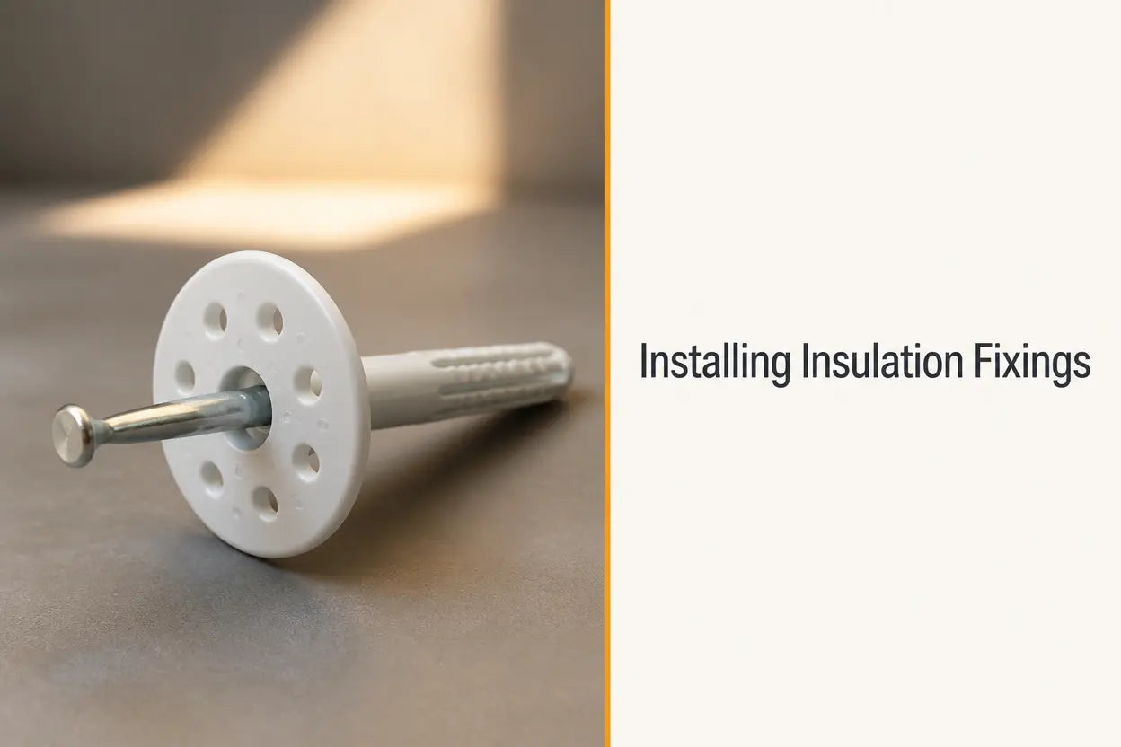
Mechanical fixings go into an insulated wall after the adhesive, and the order is the whole point: the plugs carry the weight of the boards while the bond develops, and the way each hole is drilled, cleared and set is what leaves the basecoat a flat plane to work on. This guide follows a single fixing from cure time to capped head, using the published figures for the LTX-10 hammer-in fastener that Renders World stocks across the insulation fixing accessories range.
When to Start Fixing Insulation Boards, and With What
Installing insulation fixings starts no earlier than 24 hours after the boards are bonded, on the GENDERKA EPS 032 Fasada Extra technical card, so the adhesive bed has developed grip before a drill loads it. Waiting that day out is the cheapest quality step on the elevation, because every later operation sits on the bond made underneath.
That interval is worth reading against the certified-system route, because the two documents describe different jobs. BBA Agrément Certificate 13/5018, covering the Atlas/Aval EPS external wall insulation system, has the supplementary fixings applied while the adhesive is setting, because in that certified build-up their documented role is to transfer the weight of the system to the substrate as the bond cures. The board card is the stricter of the two. Where you are fixing graphite boards outside a named certified system, take the 24-hour wait as the figure that governs and programme the drilling pass a full day behind the boarding pass.
The kit list is short, and the one item people get wrong is the bit.
- An SDS drill with a working depth stop. Consistent hole depth is what makes every plug seat to the same point across a wall.
- A 10 mm masonry bit. The LTX-10 body is 10 mm in diameter and its own sheet asks that the drilled hole diameter matches the fastener diameter, so one bit runs the whole elevation whatever the plug length.
- Plugs of the right length, matched to the graphite EPS insulation boards going on the wall. The sheet gives the sum as board thickness plus adhesive and any retained plaster plus 30 mm anchorage into the structure, and publishes a length table against it.
- A hammer, plus the cutter and caps if the heads are being recessed rather than surface-mounted.
How to Drill, Clear and Set Each Insulation Fixing
The method repeats identically across the wall, which is what makes it easy to hold together once the rhythm is set. Work board by board rather than jumping around the scaffold, and the pass finishes with every head at the same depth.
Drilling to Depth on the Fastener Sheet
Depth is measured into the substrate, not through the build-up. The LTX-10 sheet sets the drilled hole at 40 mm in standard substrates against 30 mm of anchorage, and asks for holes in solid materials to be at least 10 mm deeper than the anchorage depth. That extra 10 mm is a dust reservoir, and it is why a hole drilled to the exact anchorage figure fights you at the seating stage.
Clearing the Hole and Seating the Plug
Hole clearing has a published technique rather than a habit attached to it, and it is the step most often shortened. The sheet calls for the drill to be worked back and forth at reduced speed, repeated four times, in solid materials. Thirty seconds a hole buys the grip the assessment assumes.
- Position the fixing over adhesive. The sheet asks that the installation spot matches the area where adhesive sits behind the board, so the plug pulls against a supported face rather than a void.
- Drill square to the wall through the board and into the substrate, with the depth stop set for the substrate depth you need.
- Clear the hole with four back-and-forth strokes at reduced speed.
- Embed the body so the washer finishes faced with the insulation, which is the sheet's own wording for flush.
- Drive the pin home in one go. The sheet is explicit that a pin already driven should not be driven again, because that is what breaks them, so a head that feels wrong is replaced rather than re-struck.
Why the Disc Finishes Flush with the Board Face
Seating depth is where a good fixing pass shows itself, and it has a thermal side as well as a cosmetic one. The 60 mm plate spreads load across the board, and finishing it level with the face gives the basecoat and mesh a continuous plane to sit on. A head left proud reads through a fine grain; recessing and capping keeps the face flat and is quicker than filling later.
The figures make the case on their own. The LTX-10 declares a point thermal transmittance of 0.001 W/K surface-mounted and 0.000 W/K immersed, while the sample U-value calculations in BBA 13/5018 are built on 0.003 W/K per steel pin at four fixings per square metre, with other fixing types to be recalculated to BS EN ISO 6946:2017. A glass-fibre-reinforced polyamide pin recessed below the face is therefore the version of this detail that leaves the U-value calculation alone. The sheet builds that route into its own instructions: a plastic cutter forms the recess and a polystyrene disc closes it, which is why the EPS hole cutter and the grey EPS caps belong on the same order as the plugs.
Key Takeaway: wait the 24 hours the board card asks for, drill a 10 mm hole 10 mm deeper than the anchorage depth, clear it with four strokes at reduced speed, and seat the washer level with the board face. Recessed and capped, the fixing contributes 0.000 W/K instead of 0.001 W/K and gives the basecoat a flat plane.
How Substrate Type Changes Anchorage and Drilling
| Substrate on the LTX-10 sheet | Anchorage depth | Drilled hole depth | Hammer action |
|---|---|---|---|
| Concrete and solid masonry, use categories A and B | 30 mm | 40 mm | Permitted |
| Hollow and perforated masonry, use category C | 30 mm | 40 mm | Rotation only |
| Autoclaved aerated concrete, use category E | 50 mm | 60 mm | Rotation only |
The rotation-only instruction is a performance setting rather than a preference. The sheet states that hammer action in hollow brick and aerated concrete breaks the inner walls of the substrate and reduces pull-out resistance, so switching the drill out of impact is what preserves the figure the design relies on. Aerated concrete also takes the deeper anchorage above, which shortens the board thickness any given plug length can reach.
- Pull-out varies with what the plug lands in. The sheet declares a characteristic pull-out resistance of 0.50 kN in C12/15 concrete, rising to 0.75 kN in higher-grade concrete and in solid clay brick, with a partial safety factor of 2 in the absence of regulations.
- Assessment cover is a requirement, not a badge. BBA 13/5018 requires supplementary fixings to be covered by an appropriate ETA or UKTA; the LTX-10 holds ETA-16/0509 across use categories A to E under ETAG 014.
- Older walls get tested. Where the age and condition of the substrate differ from the wall used to establish the ETA values, that certificate calls for site-specific pull-out tests, which is the sensible route on Victorian solid brick and on previously rendered elevations.
Where the Fixing Pass Sits in the EWI Build-Up
How many plugs go in, and where, is a separate decision from how each one is installed, and it is settled before anyone reaches the scaffold. BBA 13/5018 places the number and spacing of supplementary fixings with the certificate holder, and states that in an adhesively fixed system their contribution is not counted when resistance to wind load is calculated — the bonded area at a minimum 40% is what carries it. The LTX-10 sheet gives its own recommendation for polystyrene, at a minimum of 6 per m² mid-wall and 8 per m² in corner zones below 15 metres, rising to 8 and 10 above 15 metres, and follows it immediately with the note that the recommendation does not replace the thermal insulation design. Take the density from the layout drawing rather than either figure, and the fixing pattern and spacing method works that calculation through.
Renders World supplies the hardware for both sides of that split, and the sequence either side of the fixing pass matters as much as the pass itself.
- Before: base track, adhesive at 40% coverage or better, then the cure interval above.
- After: basecoat, mesh and finish, which the EWI system build-up layers guide takes layer by layer.
- Alongside: the layer-by-layer view of which collection owns which part of the system sits on the external wall insulation hub.
Written by Mariusz Saja. Technically reviewed by Rafał Wyrzykowski. Last reviewed Aug 2026.
FAQ: Drilling, Setting and Cure-Time Questions
How much wall does a 200-piece box of plugs cover?
At the fastener sheet's mid-wall minimum for polystyrene, 200 ÷ 6 = 33.3 m²; at its corner-zone figure, 200 ÷ 8 = 25 m². A box therefore covers roughly 25 to 33 m² depending on the zone, and because a real elevation mixes both, a take-off by zone from the layout drawing is more accurate than a single average.
Can plastic-pin plugs fix mineral wool slabs?
The LTX-10 sheet names EPS and XPS polystyrene as the materials it is recommended for, and gives its fastener-count recommendation for polystyrene specifically. Nothing in it addresses stone wool, so the fixing type, length and count for a wool build-up come from the system designer against that system's own assessment.
What changes when the substrate is aerated concrete?
Two settings, both from the sheet. Anchorage goes from 30 mm to 50 mm and the drilled hole from 40 mm to 60 mm, and the hole is drilled without impact so the cell structure providing the pull-out resistance stays intact. Allow for the deeper anchorage when the plug length is chosen.
What drill bit size do insulation fixings need?
The LTX-10 is a 10 mm body and its sheet asks that hole diameter matches fastener diameter, so 10 mm covers every length in that ladder from 70 mm to 220 mm. One bit across a mixed-thickness elevation is a real time saving, though a different fastener range will state its own diameter.
Should heads be left flush or recessed and capped?
Both are documented. Flush is the sheet's standard instruction, with the washer faced with the insulation; recessed with a cutter and closed with a polystyrene disc is the immersed mount described in the same instructions. Recessing takes the point thermal transmittance from 0.001 W/K to 0.000 W/K and gives a flatter plane for the basecoat.
Order the Plugs, Cutter and Caps for Your Fixing Pass
Ordering follows the drawing: area by zone, density from the specification, length from the manufacturer table for your board thickness, plus a margin for cut boards and dropped caps. The plugs run from 70 mm to 220 mm on a single 10 mm body, in 200-piece boxes up to 200 mm and a 100-piece box at 220 mm, so check the box count rather than the box price when comparing the longest length against the rest.
- Confirm the length against the manufacturer table before ordering quantity — the LTX 140 mm plug is the common domestic size and the table on the collection page maps the full ladder.
- Add the recessing cutter and a bag of caps with the plugs if the heads are going in immersed.
- Build the rest of the order — plugs, base tracks, discs and caps — from the plugs, tracks, discs and caps shelf against your drawing, and Renders World can put the boards on the same purchase order.