
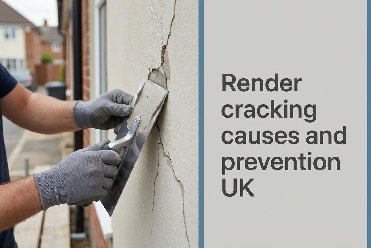
A crack in a rendered wall tells you something, so the first job is diagnosis rather than filler. Render cracking begins in one of three places — the wall behind the system, the reinforcing layer inside it, or the weather on the day the coat went on — which is why the pattern on the elevation points straight at the layer that moved. Diagnosis is the job here; routine cleaning and the scheduled care of a sound facade belong to the render maintenance page instead.
What Render Cracking Tells You About the Layer That Failed
Three mechanisms cover nearly every case of render cracking, so naming the right one first is what keeps a repair from being done twice. Each leaves a different signature on the wall.
Substrate Movement Behind the Finish Coat
Masonry, new blockwork and timber panels all move, and a thin-coat system accommodates that movement instead of resisting it. Atlas describes its silicone render as highly flexible, able to bridge thermal stress as well as hail and impact, through a high content of dedicated polymer resins and cellulose fibre reinforcement carried through the render mass.
Watch the scope on the toughness figures. The 140 J impact and 30 m/s hail resistance quoted on that sheet belong to the render as part of a named system with a specific reinforced layer beneath it, so they do not describe the material in the bucket on its own. Render cracking from substrate movement concentrates at openings and wherever two materials meet, which is why the reinforcing layer is placed to carry exactly that load.
The Reinforcing Layer, the Most Common Correctable Cause
The reinforcing layer is where most correctable render cracking starts, so the Ceresit CT 325 sheet is specific about how it goes in. Four conditions decide whether the layer works, and the first three get skipped on site far more often.
- Overlap: laps on successive belts kept to about 10 cm.
- Belt position: belts of mesh must not coincide with the joints between the boards.
- Corner reinforcement: at corner openings such as windows, additional pieces of about 20 × 30 cm go in diagonally.
The fourth condition is embedment depth. Mortar goes on with a 10–12 mm toothed trowel and the mesh is worked in until it is neither visible nor proud of the surface, and on mineral wool the boards are primed with mortar first. A mesh you can still see has not been embedded, so it carries nothing.
What the layer contributes is measurable. CT 325 is a 160 g/m² alkali-resistant E-glass fabric with 4.0 × 4.0 mm squares. Its sheet declares tensile strength of 2075 N/5 cm warp and 2180 N/5 cm weft in standard condition, and 1195 N/5 cm warp and 1220 N/5 cm weft after 28 days in 5% sodium hydroxide. That retained strength after alkali exposure is the whole point of an alkali-resistant mesh sitting in a cementitious basecoat, and it is the figure worth asking for on any roll offered as an equivalent. Where a facade or plinth carries higher mechanical loads, the sheet's own answer is two layers of CT 325 or a heavier 330 g/m² mesh.
Drying Conditions and the Window Each Sheet States
Rapid surface drying is the third source of render cracking, so the limits that prevent it are product-specific rather than generic. Atlas Silicone Render runs +5 °C to +30 °C with relative humidity below 80%, and Atlas extends use above 0 °C once Atlas Eskimo goes into the mix. Atlas Acrylic Render and Ceresit CT 74 both stop at +25 °C. Quoting one blanket window across a whole range is how a compliant job ends up recorded as a defect, so the figure always comes from the sheet in the bucket.
How to Measure a Crack Before You Decide Anything
Diagnosis needs a gauge, a knuckle and daylight, so start with the width and the sound. Measure across the fracture, then tap the surrounding area in a grid. A change from solid to hollow means the coat has separated from the substrate, which is why that single reading outranks every width below it.
Not all render cracking needs a repair, and NHBC publishes a homeowner guidance note giving the widths at which a crack stops being cosmetic. It covers cracking in the home as a whole rather than render specifically, so a builder and a warranty provider both recognise the same threshold.
| What you measure | What NHBC says |
|---|---|
| 2 mm or less | Cosmetic, usually thermal movement |
| Constantly more than 2 mm | Report it |
| Wider than 5 mm at any point | Report it |
| Wide at one end, narrow at the other | Report it |
| Diagonal or stepped, at any width | Report it |
| Visible inside and outside | Report it |
Without a tape measure on site, the edge of a one pound coin works as a gauge, since the coin is about 3 mm thick. Two further patterns help on a rendered wall. Moisture-movement cracks are usually vertical and of fairly constant width, normally under 2 mm, and they open and close as moisture levels change through the year, so a fracture that breathes with the seasons is rarely the structural one. Subsidence and heave cracks are wide at one end and narrow at the other, which is why that shape is worth reporting whatever the width.
Staining is a separate diagnosis. White mineral deposits point to efflorescence rather than cracking, so they are a salt question instead. Pressure washing a cracked elevation can widen the problem, which is why the guidance on cleaning render without damaging the surface covers the safe method in full.
Repairing Cracked Render: Matching the Route to the Mechanism
Three routes cover almost everything, so repairing render cracking is a decision about which layer is at fault instead of how the wall looks.
- Monitor. A fine crack at or under 2 mm, with no hollowness and no staining, is an appearance matter, so keep an eye on it across a full season.
- Skim. Where a fine crack stays visible through a seasonal cycle, a coat of the same render at the manufacturer's stated thickness restores the surface. Ceresit CT 76 Solar Protect is the one product in the Renders World range whose sheet claims an active self-healing effect on surface microcracks, alongside increased UV absorbers that hold colour stability.
- Cut back and re-reinforce. Where the reinforcing layer is at fault, cut back to a sound edge, re-embed mesh across the fault to the lap and embedment guidance above, then rebuild basecoat and finish in sequence.
For the third route, keep the layer inside one manufacturer's system. CT 325 carries European Technical Assessments per named Ceresit Ceretherm system — among them ETA 13/0535 in Universal EPS, 14/0127 in Universal MW and 13/0086 in Impactum — so the assessed performance belongs to the build-up, and substituting a component steps outside it. Renders World stocks that mesh as the CT 325 reinforcing mesh roll, alongside the EPS adhesives and basecoats it is embedded in. The Atlas reinforcing mesh roll is sold by roll area instead of covered area, so allow for laps separately when ordering it.
Key Takeaway: Most render cracking is a reinforcing-layer or drying-conditions story instead of a product failure. Three checks settle it on site: the lap distance the mesh sheet gives, whether belts were kept off the board joints, and whether the application temperature stayed inside the window that specific product states. Then measure the width, so that 2 mm decides whether the fracture is cosmetic.
How to Prevent Render Cracking on the Next Elevation
Preventing render cracking is mostly a specification decision taken before the scaffold goes up, so it costs nothing at that stage. Keep primer, basecoat, mesh and finish inside one manufacturer's assessed system, because the assessments are issued against named build-ups instead of individual components. Then hold three conditions on site.
- Temperature, per product: +5 °C to +30 °C for the Atlas silicone finish, +5 °C to +25 °C for the Atlas acrylic and for CT 74. Take the figure from the sheet in the bucket, and use the Atlas accelerator route rather than stretching a limit.
- Humidity below 80%: stated on both the Atlas silicone and CT 74 sheets, and worth logging, because the same coat behaves differently at 60% and at 85%.
- Reinforcement at every stress point: diagonal patches of about 20 × 30 cm at corner openings, laps at about 10 cm, belts clear of board joints, mesh fully buried and invisible.
Colour is the fourth condition and the one most often missed, because it is a structural choice instead of an aesthetic one. The Atlas sheets set a minimum light reflectance for deep shades and tie that minimum to the reinforced layer specified underneath, so the layer beneath decides how dark the elevation can safely go. The acrylic sheet asks that colours below 20% diffuse reflection be avoided and held to a tenth of the facade. Where a wall has simply aged, the route is overpainting with a silicone masonry paint, so scheduled maintenance intervals catch faults at opening corners while they are still cheap to close.
Specify the Layer That Carries the Load Before You Order
Three confirmations close out a specification that holds up against render cracking, so none of them is about the finish coat.
- The mesh grade, and its retained strength after alkali exposure.
- That the basecoat it sits in comes from the same assessed system.
- The application window for the exact product going on the wall, not for the range.
Order the mesh to covered area rather than roll area, and add for diagonal corner patches separately; the arithmetic behind that sits in the FAQ below. Renders World holds the mesh, basecoats and finishes as matched sets, so start from the alkali-resistant reinforcing mesh for the layer itself, from the Atlas Silicone Render white base where the finish is being replaced, or from thin coat render systems where primers and basecoats are needed in the same order. Render sits in Chapter 6.11 of the NHBC Standards and finishes in Chapter 9.1, which is the reference to quote in any conversation with a builder.
Written by Mariusz Saja. Technically reviewed by Rafał Wyrzykowski. Last reviewed Sep 2026.
FAQ: Diagnosing and Repairing Render Cracking
Is hairline cracking on new render normal?
Fine cracking is common while a new home dries out and while the facade works through its first seasons of movement, so it is usually cosmetic. NHBC's homeowner guidance treats a crack of 2 mm or less as cosmetic and usually down to thermal movement, and asks to be told about anything constantly wider. On a rendered wall, add the tap test, which is why a fine fracture over a hollow-sounding area counts as an adhesion problem instead.
How wide does a crack have to be before it matters?
Width is only half of it, so the shape carries the rest.
- At or under 2 mm, with no hollowness: cosmetic, monitor it.
- Constantly over 2 mm, or over 5 mm at any point: report it.
- Diagonal, stepped, or wide at one end and narrow at the other: report it at any width.
How much reinforcing mesh does an elevation need?
CT 325 lists approximately 1.1 m/m² as the amount required, which builds in an allowance for laps. Taken as 1.1 m² of mesh per square metre of wall, a 1.1 m × 50 m roll covers about 50 m² of the 55 m² it contains. Order to covered area rather than roll area, and add for diagonal corner patches separately.
What temperature can render be applied at without cracking risk?
It depends on the product, which is why one figure should never be quoted for a whole range. The Atlas silicone finish is stated at +5 °C to +30 °C, and above 0 °C once the Atlas accelerator is added. The Atlas acrylic and Ceresit CT 74 both stop at +25 °C, and humidity below 80% appears on the Atlas silicone and CT 74 sheets.
Can mesh from one brand be embedded in another brand's basecoat?
CT 325 carries its European Technical Assessments per named Ceresit Ceretherm system, so its assessed performance describes the mesh inside those build-ups rather than the roll on its own. Where a warranty or an assessment is being relied on, keep the reinforcing layer and its mortar within one manufacturer's system.
Can a cracked area be repaired without stripping the elevation?
Usually, where the surrounding render is sound and rings solid, so the repair stays local. The area is cut back to a sound edge, mesh is re-embedded across the fault following the lap and embedment guidance, and basecoat and finish are rebuilt in sequence. Full stripping becomes the honest answer when hollowness is widespread, or when the original build-up mixed components from different assessed systems.