Fibreglass mesh in UK EWI and thin-coat render systems must be overlapped by at least 100 mm at every joint — a single dimension that separates a 20-year facade from one that develops hairline cracks within its first two winters. If the overlap is too small, the render cracks along the joint line under thermal movement; if it is correct, the reinforcement layer holds the facade stable for the long term. This guide from Renders World sets out the correct overlap distances, vertical and horizontal strip layout, diagonal corner patch detailing at window and door openings, and the mesh weight to specify so you can avoid the cracking repairs that under-overlapped joints almost always produce.
The overlap rule is one piece of a wider window and opening detail strategy — the broader sequence is covered in the render detailing around windows and doors guide, and the full basecoat application process that frames how mesh is embedded sits in the basecoat and mesh reinforcement layer guide. This article zooms in on the geometry of the overlap itself.
Why Overlap Distance Matters in a UK Render System
A single strip of fibreglass mesh cannot reinforce the wall on its own. The mesh only works as intended when adjacent strips overlap enough to form one continuous reinforced layer. If two strips merely touch — or the overlap is too small — that joint becomes a weak point where movement in the wall shows up later as visible cracking through the render topcoat.
On a typical UK facade, daily temperature swings of 20–25 °C between a cold morning and a sun-warmed afternoon generate measurable differential movement. If the mesh cannot transfer that stress across its joints, a hairline crack forms precisely at the overlap line — a defect that is both structurally and cosmetically unacceptable. Industry consensus across BBA-certified ETICS systems including Atlas, Ceresit, and Roker places the minimum acceptable overlap at 100 mm, with 100–150 mm recommended as the working standard for UK external facades. Installers consistently report that the elevations they regret are the ones where overlap was treated as optional.
Key Takeaway: A minimum 100 mm overlap between adjacent fibreglass mesh strips is the baseline requirement for UK EWI and thin-coat render systems. Working to 100–150 mm is recommended practice on exposed elevations; reducing this to save mesh is a false economy that typically results in cracking repairs within 2–5 years.
Minimum Overlap Requirements by Application Context
Different wall types and detailing areas do not all move in the same way, which is why overlap guidance varies slightly by application. Use the table below as a practical rule-of-thumb to check the minimum overlap and the safer working range for the most common UK EWI and render-board situations — the comparison shows where 75 mm is acceptable and where 150 mm earns its place.
| Application Context | Minimum Overlap | Recommended Working Range | Notes |
|---|---|---|---|
| EWI system over EPS or mineral wool boards | 100 mm | 100–150 mm | Full coverage; both vertical and horizontal joints |
| Thin-coat silicone or acrylic render on masonry | 100 mm | 100–125 mm | Full coverage basecoat application |
| Render carrier boards (STS / cement board) | 100 mm | 100–150 mm | Mesh must bridge board joints by ≥50 mm each side |
| Mixed-substrate junctions (brick to blockwork, etc.) | 75 mm | 100–150 mm | Extra diagonal patch additionally recommended |
| Repair / patch over existing render | 75 mm | 100 mm | Feather edges; embed into fresh basecoat |
| Diagonal corner patches at window/door openings | 150 mm into field mesh | 200 mm | Applied before field mesh, not on top |
How to Lay Out Mesh Strips on a Standard Elevation
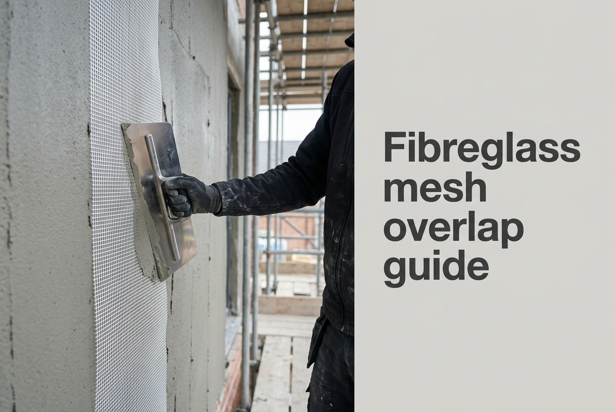
The standard approach on a flat elevation is to run mesh strips vertically from soffit to base track, overlapping each successive strip by 100–150 mm on its right-hand edge. Vertical orientation aligns with how basecoat is typically applied — from the top down in horizontal passes — and means that gravity assists the embedding process rather than working against it. The roll is stood vertically on the floor or scaffold board, unrolled upward against the fresh basecoat from the EPS adhesive and basecoat layer, and pressed in progressively with a stainless steel trowel.
Horizontal orientation is acceptable and sometimes preferred around window and door openings, or where the wall is shorter than a standard roll width. Where horizontal strips are used alongside vertical ones, the same 100 mm minimum overlap applies at every joint regardless of orientation. The critical rule is that no joint from the horizontal run should coincide with a joint from the vertical run — stagger them by at least half a roll width to prevent any cross-pattern of weak seams forming across the face.
- Align strip edges before embedding: Hold the mesh against the wet basecoat and mark the overlap zone lightly with a scratch before pressing — this keeps the 100 mm zone in position under the trowel rather than drifting as the mesh is worked in.
- Never butt-join two strips: A butt joint provides zero overlap and is a guaranteed failure point. Even where space is constrained — around reveals, behind pipes, at internal corners — cut a strip to allow a minimum 75 mm overlap rather than letting two edges meet.
- Keep mesh in the outer third of the basecoat depth: Mesh sitting flush with the surface shows through the topcoat; mesh pressed hard against the insulation board contributes almost no tensile value. Aim for the mesh to sit in the outer third of the basecoat — typically 2–3 mm depth within a total 4–6 mm basecoat thickness.
- Work your trowel vertically, not diagonally: When pressing the overlap zone, always work your trowel vertically downward in the direction of the overlap. Trowelling across or diagonally displaces the lower strip and creates an ugly ridge that shows through the finished topcoat.
Diagonal Reinforcement Patches at Window and Door Openings
Window and door corner detailing is the area where even experienced installers most frequently under-specify the mesh. The corners around openings are natural hotspots for structural movement — standard field mesh alone will not stop cracks here, and a dedicated diagonal patch must be installed at every corner to handle that 45-degree tension. The patch is typically 300 mm × 200 mm, positioned diagonally at 45° across each corner, and it is applied to the freshly applied basecoat before the field mesh goes on — not embedded on top of it. This sequencing matters: the diagonal patch must sit deeper in the basecoat, closer to the insulation board or substrate, so that the field mesh overlaps it from above. Reversing the order leaves the patch at the surface, which renders it ineffective.
Around the full perimeter of each opening — sill, jambs, and head — an additional 100 mm wide strip of mesh should be wrapped from the reveal face onto the main elevation, overlapping into the field mesh by at least 100 mm. This return strip stops the render from cracking and peeling away where the window reveal meets the main wall — a common weak point because the wall and the window frame heat up and cool down at different rates. Where render corner beads are being installed at the same detail, the mesh must pass behind the bead's wing rather than being cut flush to the bead edge — failure to do this leaves an unreinforced strip along every external corner.
Choosing 150 g/m² or 160 g/m² Mesh for Your Project
The two mesh products in the Renders World range — the Atlas Fibreglass Mesh 150 g/m² and the Ceresit CT325 Mesh 160 g/m² — represent the standard performance range for UK external facade applications. The Ceresit mesh is slightly heavier at 160 g/m², which gives it a little more strength and a firmer feel during application. Both products are alkali-resistant, so they are designed to stay stable inside cement-based basecoats, and both achieve the ≥ 2,000 N/50 mm tensile threshold required by BBA-certified ETICS specifications.
Choose Atlas 150 g/m² for standard domestic EWI and routine silicone render work over EPS where you need a reliable general-purpose facade mesh. Choose Ceresit CT325 160 g/m² where the system specification already calls for Ceresit, where the elevation is more exposed to weather (coastal, elevated, south- or west-facing), or where you want a slightly heavier mesh for better handling stability and added confidence at vulnerable ground-floor areas. In either case, neither product should be substituted for a lighter-weight mesh below 130 g/m² on an external UK facade — lightweight meshes are designed for internal plastering and will not provide sufficient tensile load transfer in an external EWI context.
How to Diagnose Common Overlap Failures on Site
If you spot vertical cracks appearing at regular 500–600 mm intervals across a wall, it almost always indicates that the installer cut the mesh to a standard width and butted the edges instead of overlapping them. The spacing corresponds to the roll width minus the intended overlap, confirming that the overlap was skipped. This failure mode is especially common when installers are under time pressure and pre-cut all strips to the same length before starting — a method that is efficient for labour but incompatible with achieving a correctly overlapped joint without a deliberate check measure on every strip. The wider catalogue of crack causes and prevention strategies is covered in the render cracking causes and prevention guide.
A second common failure pattern is a horizontal crack running continuously across an elevation at the same height as a scaffold lift. This indicates that mesh strips were cut at the scaffold board level and the upper and lower lifts were not overlapped — they were butted at the working height boundary. Always plan mesh strip lengths to pass through scaffold-lift lines by at least 150 mm, treating the overlap zone as a structural detail, not an incidental result of strip length.
- Diagonal cracks at 45° from window corners: Missing or incorrectly applied diagonal corner patches. Remedy requires cutting back to the crack, applying a new diagonal patch embedded in fresh basecoat, and reinstating the topcoat.
- Map cracking across the full elevation (no regular pattern): Mesh embedded too close to the surface, or basecoat applied too thinly before embedding. The mesh is visible at the surface under oblique light, confirming incorrect depth placement.
- Cracking along the reveal-to-elevation junction: Mesh return strip was omitted or too narrow. This is the most common failure on window-reveal details and is consistently underappreciated on first-fix EWI installations.
Written by Mariusz Saja. Technically reviewed by Renders World Team. Last reviewed Jun 2026.
FAQ — Mesh Overlap, Quantity, and Site Practice
What is the minimum overlap for fibreglass mesh in an EWI system, and is it difficult to get right?
The minimum overlap between adjacent fibreglass mesh strips in a UK EWI or thin-coat render system is 100 mm. Working to 100–150 mm is the recommended standard on external UK facades, particularly on exposed or high-movement elevations. Anything less creates a weak joint that is vulnerable to cracking under thermal and structural movement. In terms of difficulty: embedding mesh with correct overlaps is manageable for a competent DIYer on a small, straightforward area. For a full EWI facade, however, most homeowners use a professional installer so the basecoat-and-mesh layer is applied consistently and to the correct depth. If you are unsure, it is sensible to confirm the system build-up and quantities before ordering rather than risk having to redo the work later.
Do diagonal corner patches go on before or after the field mesh?
Diagonal reinforcement patches at window and door corners must be applied before the field mesh, not on top of it. The patch is embedded into the freshly applied basecoat first, sitting deeper in the coat. The field mesh is then applied over it, overlapping the patch by at least 100–150 mm. Reversing this sequence leaves the patch near the surface, where it provides minimal tensile benefit and is liable to telegraph through the topcoat as a visible square.
How much fibreglass mesh do I need per m² of wall, and how can I reduce waste at overlaps?
As a simple planning rule, order 10–15% more mesh than your measured wall area to allow for overlaps, corner patches, and reveal details. In practice, a 50 m² roll will usually cover about 43–45 m² of actual wall area once those details are included — so a 90 m² facade would normally need two rolls rather than one. To minimise off-cut waste, plan your strip layout before cutting. Start from a fixed reference point such as a corner bead or base track, mark the overlap zones, and pre-measure each strip length to run through scaffold-lift lines rather than stopping at them. Avoid pre-cutting all strips to identical lengths; a measured-as-you-go approach wastes less material than a batch-cut approach that ignores the variable geometry of real elevations.
Are fibreglass mesh off-cuts recyclable, and how should they be disposed of on site?
Fibreglass mesh off-cuts should not go into standard UK recycling bins or mixed recycling skips. Because the mesh is coated to resist chemicals in the basecoat, it requires specialist composite recycling, which is rarely an option for standard building projects. On site, off-cuts should be bagged and disposed of as general construction waste via a licensed waste carrier; they must not be burned or buried. The environmental case for minimising mesh waste is therefore practical as well as principled: careful strip planning that reduces off-cuts is both the most cost-efficient and the most environmentally responsible approach. Where a project generates significant off-cut volume, composite waste specialists operating in the UK can accept fibreglass material for mechanical recycling into lower-grade construction aggregate.
Does it matter where in the basecoat the mesh actually sits?
Yes — significantly. Mesh embedded in the outer third of the basecoat (2–3 mm depth within a 3–5 mm layer) sits in the tensile zone where it actively works under thermal movement. Mesh pressed flat against the insulation contributes almost no tensile value because the basecoat above it carries the entire load alone, and mesh left at the surface telegraphs through the topcoat as a visible diamond pattern. The two-pass application — first basecoat layer applied, mesh pressed in while wet, second basecoat layer floated over — places it correctly.
Where to Order the Right Mesh for Your Overlap-Critical Build-Up
Correct fibreglass mesh overlap is not an optional refinement — it is the difference between a render system that performs for 20+ years and one that requires remedial work within its first decade. The rules are straightforward: a minimum 100 mm overlap on all field joints, 300 × 200 mm diagonal patches at every opening corner installed before field mesh, mesh returns around reveals of at least 100 mm, and a mid-depth position within the basecoat layer. Selecting the right mesh weight for the exposure class — Atlas 150 g/m² for standard domestic EWI, Ceresit CT325 160 g/m² for higher-exposure or Ceresit-specified systems — ensures the reinforcement contributes full tensile performance from the outset. Browse the full fibreglass mesh range at Renders World to choose the roll that matches your system and exposure, then allow 10–15% extra over your measured wall area for overlaps, corner patches, and reveal returns — all available for next-day UK delivery alongside the matching basecoat, beads, and reinforcement details for the complete build-up.