
Description
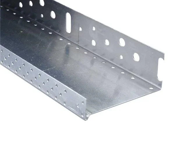
The 53 mm base track is where base-track work crosses from detailing to full facade insulation. At 53 mm channel width it is the first profile in the standard range sized for 50 mm primary boards across the main wall — the entry thickness on enhanced domestic specifications, budget-conscious retrofits, and phased programmes targeting a modest U-value improvement. Integral drip edge, perforated web for base-zone ventilation, 0.6 mm aluminium gauge, 2.5 m length.
What the 53 mm Base Track Does in a UK EWI System
The 53 mm base track is the entry-level full-facade aluminium starter profile in UK external wall insulation systems — a 2.5-metre length sized to anchor 50 mm insulation boards across the main wall rather than at detail areas alone, with a 0.6 mm gauge, integral drip edge, perforated web, and clip-on mesh-carrier compatibility. It is the third-narrowest profile in the insulation fixing accessories range and the first that carries the full board weight of a primary insulation course.
Its commercial position is the budget-conscious or thermally moderate specification: retrofits where 50 mm boards meet the calculated U-value target, smaller commercial elevations needing a modest upgrade, phased programmes where 50 mm is the first stage of a future over-cladding build-up, and properties where planning or sight-line constraints rule out thicker boards. The track delivers the same installation quality as wider profiles at lower material cost per linear metre — the right call when 50 mm is the answer the calculation gives.
Why Trade Specifiers Choose the 53 mm Base Track
- Entry-thickness track for full-facade insulation: the 53 mm channel takes 50 mm EPS or XPS boards with the 3 mm tolerance needed for adhesive and seating — the first profile in the range that handles a primary main-wall course rather than detail closures alone.
- Perforated web for base-zone ventilation: punched apertures along the horizontal shelf let residual construction moisture and minor vapour drive escape from behind the lowest board course rather than accumulate against the wall base, protecting the long-term drying performance on new masonry still holding construction moisture.
- Integral drip edge manages wall-base rainwater: the formed lower lip projects beyond the wall face, shedding rainwater and ground splash-back away from the insulation base — at the most weather-exposed zone of any EWI system, the detail that prevents basecoat erosion and board-edge saturation.
- Corrosion-resistant aluminium at service-life match: the natural oxide layer withstands prolonged moisture and the alkaline chemistry of basecoat and adhesive without degrading, matching the expected service life of the wider EWI system rather than failing early at the most exposed component.
- Cost-efficient at the standard spec: where the calculation specifies 50 mm boards, the 53 mm track gives the correct channel width without the material cost of oversized profiles forced to hold thinner boards, and on a 60 m perimeter run that efficiency compounds across the material list.
- Direct pairing with 50 mm EPS from the range: works with 50 mm graphite EPS from the EPS insulation boards range at lambda 0.032 W/mK, plus 50 mm XPS for ground-contact and below-DPC plinth detailing where the track doubles as a moisture-break shelf.
Technical Specifications — 53 mm Base Track Data Highlights
| Parameter | Value |
|---|---|
| Profile width | 53 mm |
| Length | 2,500 mm (2.5 m) |
| Material | Aluminium alloy |
| Gauge (thickness) | 0.6 mm |
| Finish | Natural aluminium (mill finish) |
| Drip edge | Yes — integral lower lip extending beyond wall face |
| Perforated web | Yes — punched apertures along horizontal shelf |
| Pre-installed mesh | No — clip-on mesh-carrier profile required |
| Recommended fixing centres | 300 mm |
| Suitable insulation thickness | 50 mm boards |
| External corner detail | 45° mitre cut both sides |
| Recommended expansion gap | 2–3 mm between adjacent lengths |
| Recommended fixing | 6 mm masonry bit · wall plug + screw |
| Corrosion resistance | Inherent aluminium oxide layer |
How the 53 mm Base Track Installs in a Render or EWI System
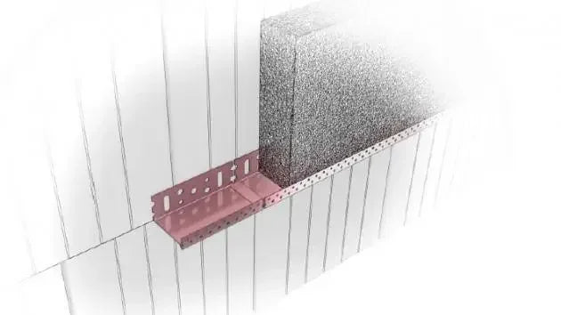
The 53 mm base track enters the build-up as the first installed component on the elevation, ahead of any insulation board. Establish the datum using a laser level transferred around the full perimeter — typically 150 mm above finished ground level and directly above the DPC — and snap a chalk line along it. Pre-drill at 300 mm centres with a 6 mm masonry bit, fix through into the substrate with wall plugs and screws suited to the masonry, leave a 2–3 mm expansion gap between lengths, and mitre-cut external corners at 45° so the drip edge wraps continuously.
- Board seating: apply adhesive to the rear face of each 50 mm board and seat it squarely on the horizontal shelf with the perforated web below.
- Web orientation: confirm the perforations face downward toward the substrate so trapped moisture can escape.
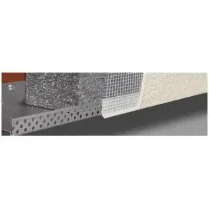
- Mesh integration: snap the clip-on mesh-carrier onto the front lip to carry fibreglass mesh into the basecoat above.
The mechanical anchorage for the board courses above the track is where wind-load performance is set. The step-by-step insulation fixings installation guide covers substrate assessment and anchorage in detail, and the fixing pattern and spacing calculation method sets out the layout aligned with ETAG 014 wind-load categories.
Installation Notes — Substrate Pull-Out, Ventilation Apertures, Mitre Discipline
Substrate pull-out is the variable that changes meaningfully at this width. At 50 mm board thickness the full board weight plus adhesive plus the dead load of every course above bears on the base-track fixings — significantly more than at the 23 mm or 33 mm detail sizes. On dense masonry, standard nylon frame plugs at 300 mm centres comfortably carry the load; on aerated block or lightweight aggregate the certified pull-out per anchor drops measurably, and the practical answer is longer plugs with greater embedment plus a torque check on three anchors per elevation before any board is loaded.
Ventilation apertures along the perforated web are an owned detail of this profile that lower-spec alternatives lack. The apertures should sit downward-facing toward the substrate so trapped moisture and minor vapour drive can escape rather than accumulate. Inverting the track defeats the geometry, so a visual check of the perforation orientation before fixing the first length saves an unwelcome correction later.
Mitre and Corner Discipline
Both meeting lengths at every external corner should be mitre-cut at 45° for continuous drip-edge geometry around the corner without a butted joint that creates a moisture trap. A small aluminium mitre box and standard tin snips deliver consistent cuts on 0.6 mm gauge. At internal corners, butt one length into the adjacent wall face and seal the junction with a bead of EWI-compatible sealant to keep moisture from tracking behind the track.
Pro Tips From UK Installers Using the 53 mm Base Track
As the first load-bearing main-wall track in the range, the 53 mm rewards a few habits that a detail-only profile never needs.
- Torque-check three anchors per elevation before loading insulation. At 50 mm board weight plus the courses above, the fixings carry more load than on detail tracks; two minutes confirming pull-out on three test anchors prevents the slow track sag that only emerges after several courses are bonded — when correction means stripping board work.
- Confirm perforation orientation on the first length. Orientation is easy to invert by habit when shifting from a non-perforated detail profile; a ten-second check that the apertures face downward toward the substrate locks it for the whole elevation.
- Order to elevation length, not perimeter total. A 6 m front elevation needs three 2.5 m lengths with trimming allowance; add one length per external corner for mitre waste and one per two internal corners for the practical figure.
- Seal internal corners on day one, not at snagging. The sealant bead belongs at the moment the track is fixed; doing it later means cutting back basecoat to reach the corner, which leaves a visible scar.
- Plan the transition to detail tracks before fixing the main run. Where the 53 mm main-wall track meets the 33 mm closure at a lintel return, mark both transition points on the chalk line first — fixing the 53 mm then finding the 33 mm does not align at the datum is a common avoidable rework.
How the 53 mm Base Track Compares to Neighbouring Base Track Profiles
The standard base track range shares one aluminium alloy, a 0.6 mm gauge, and a 2.5 m length across every width — only the channel changes to match board thickness. The 53 mm is the entry main-wall track, sitting above the 33 mm closure profile and below the 83 mm that carries the most common 80 mm retrofit thickness. Renders World stocks the full ladder, so mixed-thickness elevations run one datum line throughout.
| Variant | Key spec | When to choose |
|---|---|---|
| 33 mm base track (2.5 m) | 30 mm boards · drip edge | Lintel heads, deeper reveal closures |
| 53 mm base track (this product) | 50 mm boards · perforated web | Entry-thickness main-wall course |
| 83 mm base track (2.5 m) | 80 mm boards · perforated web | Most common domestic retrofit |
Is the 53 mm Base Track Right for Your Project?
- Anchoring 50 mm EPS or XPS across the main wall: the 53 mm is the entry-thickness main-wall track for enhanced domestic specifications, budget-conscious retrofits, smaller commercial upgrades, or phased programmes where 50 mm is the first stage of a future over-cladding build-up.
- Stepping down to detail-area thicknesses? The 33 mm base track in the comparison table above takes 30 mm boards on lintel heads, soffit returns, and deeper reveal closures — the closure thickness that complements 50 mm main-wall insulation around openings.
- Stepping up to the most common retrofit thickness? The 83 mm base track in the table matches 80 mm boards on the volume UK domestic retrofit — solid-wall houses upgrading to enhanced performance and properties targeting a tighter U-value than 50 mm delivers.
- Need the boards to match? The graphite EPS insulation boards stock 50 mm at lambda 0.032 W/mK in matching pack sizes, ready to pair with the track on one order.
- Need a heavy-duty profile for exposed sites or multi-storey work? The wider and heavier-gauge profiles in the base track and fixings range provide additional rigidity and wind-load resistance where the standard 0.6 mm gauge does not match the project loading.
FAQ — 53 mm Base Track Coverage, Thickness, Ordering
Does the 53 mm channel only accept exactly 50 mm boards?
The 53 mm channel is sized for 50 mm boards with a 3 mm tolerance for adhesive and seating. Boards between 48 mm and 50 mm sit correctly; thinner boards leave a loose fit that needs shimming during cure; boards thicker than 50 mm refuse to seat fully and either point-load the channel lip or project beyond the track edge. For 30 mm closures use the 33 mm track; for 80 mm primary insulation step up to the 83 mm track.
Is 50 mm insulation enough to meet current building regulations?
A 50 mm graphite EPS board at lambda 0.032 W/mK typically achieves a wall U-value of approximately 0.45–0.55 W/m²K on a standard masonry substrate, subject to the existing wall construction and the specific calculation method. This may satisfy phased improvement programmes or particular project conditions, though deeper retrofits targeting the 0.30 W/m²K threshold under current Approved Document L guidance generally require thicker boards. A qualified energy assessor confirms the exact thickness needed for any given project.
Can the 53 mm track be used on a curved wall section?
Standard aluminium base tracks are designed for flat or gently angled elevations and do not flex to follow a tight wall curve without kinking. Dedicated flexible base tracks with segmented or slotted designs are available for genuinely curved walls. For a straight run adjacent to a curved section, the 53 mm standard track remains the correct choice — fix it to the straight run, seal the transition joint where the curve begins, and transition to the flexible profile for the curved length.
How many tracks do I need per elevation?
Divide the total linear run of the base line in metres by 2.5 to calculate the number of 2.5 m lengths. Add one extra length per external corner to account for mitre-cut waste, and one length for every two internal corners or step changes in DPC height. On a typical semi-detached front elevation of approximately 6 m linear run with two external corners, four lengths provide comfortable coverage with trimming allowance.
When should I specify a heavy-duty profile instead of this standard track?
The 0.6 mm standard gauge suits the majority of domestic and low-rise commercial EWI projects where 50 mm boards sit on standard-exposure elevations. A heavier 1 mm profile is designed for higher-load applications — thicker boards, multi-storey facades, or exposed coastal and upland sites where greater wind-load resistance and structural rigidity are required. For a 50 mm board on a standard domestic wall, the 0.6 mm gauge provides more than adequate support at lower material cost.
What do the perforations along the track shelf actually do?
The punched apertures along the horizontal web let residual construction moisture and minor vapour drive escape from behind the insulation rather than accumulate against the wall base. On new-build masonry still carrying construction moisture in the brickwork or blockwork, the ventilation pathway protects the long-term drying performance of the assembly. The perforations should face downward toward the substrate when the track is fixed — orientation matters and is easy to invert by habit.


