
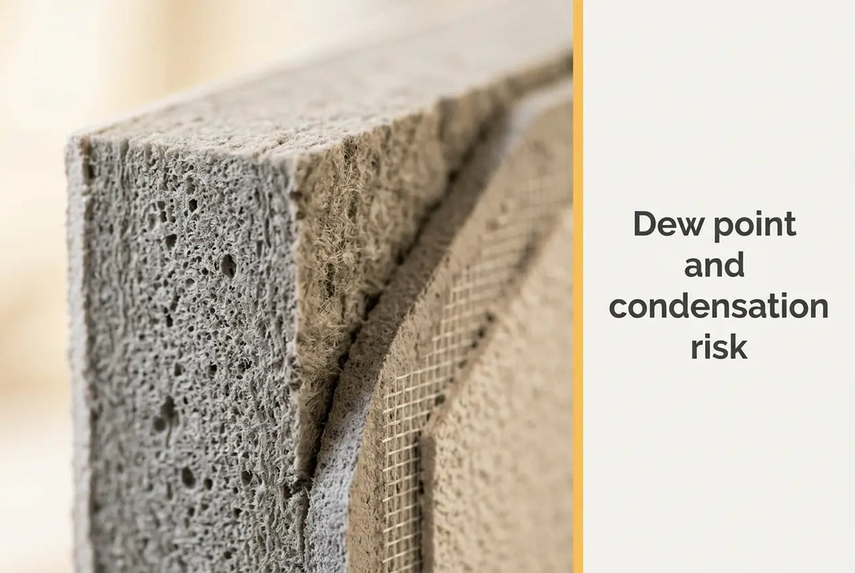
Moving the dew point out of the masonry and into the insulation layer is the single largest change external wall insulation makes to the moisture behaviour of a solid wall, and it is the reason a correctly specified system leaves the structure drier than it found it. Whether that shift actually happens is a matter of calculation rather than assumption.
This guide sets out the mechanism, the two calculation routes used in UK practice, and the material properties that decide whether a build-up keeps drying outward. It sits alongside the layer-by-layer walkthrough in the EWI system build-up guide and takes the hygrothermal side further than a component list can. Renders World supplies the boards, adhesives and renders these calculations are run on, so every figure below is transcribed from a manufacturer or standards document read for this article.
How Dew Point Condensation Risk Moves When You Insulate Externally
Dew point condensation risk external wall insulation must manage is settled by calculation rather than judgement, and ISO 13788:2012 gives the simplified method used to test every interface in the build-up for interstitial condensation. The standard covers two questions at once: the internal surface temperature below which mould growth becomes likely, and the risk of condensation forming inside the construction through vapour diffusion.
The physics is straightforward once the temperature profile is drawn. On an uninsulated solid wall the masonry itself carries the whole temperature gradient, so the coldest part of the build-up sits within the structure. Bond insulation to the outside face and the masonry moves onto the warm side of the barrier, staying close to indoor temperature through its full depth while the board carries the gradient instead. A 100 mm graphite EPS 032 Fasada Extra board declares a thermal resistance of 3.10 m²K/W, and that resistance is what shifts the cold zone outward, away from the brick.
- The masonry warms up. With the gradient transferred to the board, the structure spends the heating season above the temperature at which vapour reaching it would condense.
- The cold face moves outboard. The lowest temperature in the build-up now sits in the outer part of the insulation, a material that holds no significant liquid water.
- Drying stays available. A vapour-permeable render finish keeps an outward escape route open, so any trace moisture that does form has somewhere to go.
That third point is the one that decides the outcome. Relocating the dew point is only half the job; the build-up also needs a drying path, and confirming both is what the calculation is for.
Which Condensation Risk Analysis Method to Use, and When
Two documented routes are available in UK practice, and choosing between them is a judgement about which moisture mechanisms are actually in play on the wall in front of you. Both feed the same design decision: whether the specified build-up stays dry across the year.
The Simplified Steady-State Method Under ISO 13788:2012
The simplified route, widely called the Glaser method on UK drawings, plots temperature and vapour pressure through each layer and reports condensation wherever the vapour-pressure curve meets saturation. ISO 13788:2012 is explicit about what it leaves out: variation of material properties with moisture content, capillary suction and liquid moisture transfer within materials, air movement into the component through gaps, and the hygroscopic moisture capacity of materials. For a sound masonry substrate with a moderate moisture load, none of those omissions is decisive, which is why the simplified method is the working tool on most projects. The same standard also covers drying time for water trapped between two high vapour resistance layers, which is the calculation to reach for when a wall is being insulated over an existing impermeable coating.
Numerical Simulation for Higher-Risk Walls
Where the mechanisms ISO 13788:2012 excludes are the ones in question — driving rain on an exposed elevation, a porous pre-1919 brick with a high baseline moisture content, solar-driven redistribution on a south face — the numerical route is the honest answer. BS EN 15026:2007 covers assessment of moisture transfer by numerical simulation, and BS 5250:2021, published on 31 July 2021, is the UK code of practice for management of moisture in buildings that frames the wider assessment. The moisture-migration mechanics behind these cases are worked through in more depth in the interlayer condensation physics guide.
| Route | Document | Suits | Documented limitation |
|---|---|---|---|
| Simplified steady-state | ISO 13788:2012 | Sound masonry, moderate moisture load | Excludes liquid transfer, capillary suction, air movement, hygroscopic capacity |
| Numerical simulation | BS EN 15026:2007 | Porous solid wall, driving rain, heritage fabric | Scope confirmed as title and publication date only this session |
| Governing code of practice | BS 5250:2021 | Whole-building moisture strategy | Scope confirmed as title and publication date only this session |
How to Choose Insulation for Vapour Behaviour
Vapour resistance is expressed as a resistance factor, and its practical consequence is simple: the higher the factor, the more the layer slows outward vapour movement, so the more the drying path depends on everything outboard of it. Matching that behaviour to the substrate is the decision that makes or breaks the calculation.
Graphite EPS on Sound Masonry and Cavity Walls
The EPS insulation boards stocked here declare λD 0,032 W/mK to EN 13163:2012+A1:2015, so a given thermal resistance is reached in a thinner board than a lower-grade material would need — which matters at reveals, sills and eaves where depth is constrained. Graphite EPS performs best on substrates with a manageable moisture load: modern cavity walls, dense brick and concrete blockwork. Board depth against target performance belongs to the U-value and insulation thickness guide, which owns that calculation; the declared resistance per thickness comes from the board's own technical card rather than from dividing thickness by lambda.
One installation detail from that card rarely reaches specification notes and is worth carrying to site. Because the boards are steel-grey, the datasheet requires their surface to be protected from direct sunlight during storage and installation, calls for the face to be sanded immediately before bonding to improve adhesion, and sets mechanical fixing no earlier than 24 hours after the boards are bonded. Holding that 24-hour interval is a step worth getting right, because it is what lets the adhesive develop before the fixings load it.
Mineral Wool Where Outward Drying Governs
Where a porous solid wall needs the most open drying path available, mineral wool insulation is the specification that keeps vapour moving outward with the least restriction, which is why it is the usual choice on pre-1919 brick and on heritage fabric. The Rockwool Plus 80 mm slab is the common starting point on retrofit elevations, paired with the wool-compatible adhesive rather than a standard EPS product. No declaration of performance for these slabs could be retrieved this session, so no density, permeability or reaction-to-fire figure is stated for them here; the material comparison at board and slab level is handled in the graphite EPS and mineral wool comparison.
Key Takeaway: External wall insulation relocates the dew point out of the masonry and into the board, and the specification holds only where a vapour-permeable finish keeps the drying path open outboard of it. Run the simplified ISO 13788:2012 method on sound masonry and the numerical route of BS EN 15026:2007 on porous or driving-rain elevations. Graphite EPS at λD 0,032 W/mK suits substrates with a manageable moisture load; mineral wool is the route where maximum outward drying governs.
Why Ventilation Decides Whether the Calculation Holds
A condensation risk analysis takes indoor humidity as an input, so the calculation is only as good as the ventilation that delivers it. As a wall is insulated and draught paths close, deliberate ventilation provision is what keeps the assumed conditions real, and Approved Document F, Volume 1 sets the rates. Paragraph 1.1 of the 2026 edition puts it plainly: without adequate ventilation, mould and internal air pollution might become hazardous to health.
- Whole dwelling rate. A minimum of 0.3 litres per second per m² of internal floor area, and separately a minimum set by bedroom count — 31 l/s for three bedrooms. On a 90 m² three-bedroom house, 0.3 l/s/m² × 90 m² = 27 l/s, which is below the 31 l/s bedroom figure, so 31 l/s governs the design.
- Extract at source. Intermittent extract of 15 l/s in a bathroom and 30 l/s in a kitchen with a cooker hood extracting outside, rising to 60 l/s where the hood does not extract outside.
- Purge capacity. At least four air changes per hour direct to outside in each habitable room.
- Timing. The 2026 edition takes effect on 24 March 2027 for work not connected with higher-risk building work, and on 24 September 2027 where it is — so specifications written now should identify which edition applies.
Approved Document F also recognises the wall type this article keeps returning to. Paragraph 0.5c allows that historic buildings with a vapour-permeable construction, which both absorb moisture and readily allow it to evaporate, may not need to comply fully — the same breathability logic that pushes those walls toward the numerical assessment route. Across the wider silo, the layer that owns each part of this behaviour is set out in the external wall insulation category, where the boards, adhesives, mesh and finishes are grouped by their position in the build-up.
Where to Apply Extra Care on High-Risk Walls
Certain wall types reward a closer look at the specification stage, and recognising them early is what keeps the work straightforward later.
- Porous pre-1919 solid brick. High absorption and an elevated baseline moisture content make this the clearest case for the numerical route, with the most vapour-open insulation and finish the project allows.
- Exposed and coastal elevations. Driving rain deposits liquid water on the finish, so board joints and fixing positions need detailing that keeps water out of the insulation. Fixing layout is covered in the fixing pattern and spacing guide.
- High internal moisture generation. Run the analysis on realistic occupancy rather than default conditions, and size ventilation to the Approved Document F rates above so the assumption behind the calculation is the one the building actually delivers.
- Mixed substrates on one elevation. Concrete lintels, blockwork and brick conduct differently, so continuous insulation carried into reveals and soffits is what removes the localised cold spots at their junctions.
How to Specify a Dry Build-Up: Pre-Installation Checks
Every dew point condensation risk external wall insulation review comes down to a short sequence of confirmations, each of which can be evidenced from a document before an order is placed.
- Confirm the substrate type, its condition and any existing coating that would restrict outward drying.
- Select the calculation route — simplified under ISO 13788:2012, or numerical under BS EN 15026:2007 where liquid transport or driving rain dominates.
- Take the insulation's declared thermal resistance for the specified thickness from its own technical card, not from thickness divided by lambda.
- Check that the finish keeps a vapour-permeable path open outboard of the insulation.
- Size ventilation against Approved Document F and confirm which edition applies to the work.
- Detail reveals, soffits, plinths and parapets for continuous insulation before the first board is bonded.
Work through those six in order and the hygrothermal case for the build-up is documented rather than assumed. The Renders World team can supply the manufacturer technical cards and declarations behind each material in a specification, which is what a Building Control submission or a retrofit assessment will ask for.
Written by Mariusz Saja. Technically reviewed by Rafał Wyrzykowski. Last reviewed Aug 2026.
Frequently Asked Questions
Does external wall insulation remove condensation risk altogether?
It relocates the risk rather than deleting it. The masonry moves to the warm side of the barrier and the coldest plane moves into the board, which is a far more forgiving location, but the build-up still needs a vapour-permeable finish outboard of the insulation and ventilation sized to Approved Document F rates. Get both right and the wall runs dry through the heating season.
Graphite EPS or mineral wool for vapour behaviour?
Substrate porosity decides it. Graphite EPS at λD 0,032 W/mK to EN 13163:2012+A1:2015 reaches a given resistance in less depth and suits cavity walls, dense brick and blockwork with a manageable moisture load. Mineral wool is the route where a porous solid wall or heritage fabric needs the most open outward drying available. No declaration of performance for the stocked slabs was retrievable this session, so no numerical property is quoted for them.
Which standard governs a condensation risk analysis?
ISO 13788:2012 provides the simplified calculation for internal surface temperature and for interstitial condensation from vapour diffusion. BS EN 15026:2007 covers assessment of moisture transfer by numerical simulation, and BS 5250:2021 is the UK code of practice for management of moisture in buildings. Which one a project needs follows from whether liquid transport and driving rain are significant on the elevation.
What ventilation rates should sit alongside the insulation?
Approved Document F, Volume 1, 2026 edition sets a whole dwelling minimum of 0.3 litres per second per m² of internal floor area, with a bedroom-count minimum of 31 l/s at three bedrooms, whichever is higher. Add intermittent extract of 15 l/s in bathrooms and 30 l/s in kitchens with a hood extracting outside, plus purge capacity of four air changes per hour in habitable rooms.
Can a wall with an existing impermeable coating be insulated externally?
Yes, with the drying question answered first. ISO 13788:2012 includes a method for the time taken for water in a layer between two high vapour resistance layers to dry out, and for the condensation risk elsewhere in the component during that drying. Running that calculation, or removing the coating, is what turns a doubtful case into a documented one.
What should be checked after installation?
Keep the outward drying path clear and the ventilation working: confirm extract fans still meet their rates, keep background ventilators open, and keep the render finish clean so its permeability is not reduced by heavy organic growth. Those three checks preserve the conditions the original calculation assumed.