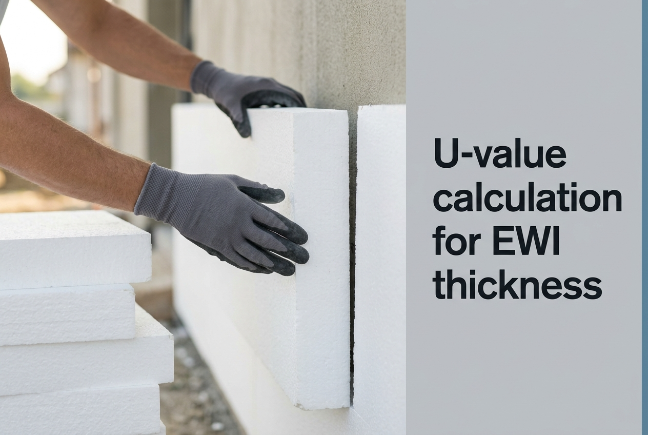
Selecting the correct insulation thickness for an external wall starts with a single number — the U-value — and every professional working on EPS insulation boards in the UK needs to understand how that number is calculated, what influences it, and where the regulatory targets sit for new-build and retrofit projects. This guide walks through the complete U-value calculation method for externally insulated walls, from gathering material data and surface resistances through to the final arithmetic that determines whether your chosen board thickness passes or fails Building Control.
The methodology follows BS EN ISO 6946 (the European standard for calculating thermal resistance and transmittance of building elements) and the conventions set out in BR 443 (BRE's guidance document defining how U-values are calculated for UK Building Regulations purposes). If you are already familiar with the full EWI system build-up and its functional layers, the calculation below shows how each of those layers contributes a measurable thermal resistance to the overall assembly — and how changing the insulation thickness shifts the final U-value toward or away from the target.
What a U-Value Actually Measures — And Why the Target Matters
A U-value (thermal transmittance) measures how much heat energy passes through one square metre of a building element for every degree of temperature difference between inside and outside, expressed in W/m²K. A lower U-value means less heat escapes, so the wall performs better as an insulator. For a typical uninsulated 215 mm solid brick wall, the U-value sits at approximately 2.0–2.1 W/m²K — meaning substantial heat loss that drives high energy bills and poor EPC ratings.
UK Building Regulations set maximum permissible U-values for each building element. Approved Document L (2021 edition, England) requires new-build external walls to achieve 0.26 W/m²K as the limiting fabric standard, while retrofit walls must reach 0.30 W/m²K where technically feasible. The Future Homes Standard tightens the new-build target further toward a notional 0.18 W/m²K, which demands thicker insulation and careful attention to thermal bridging at junctions. Understanding the calculation method lets you specify the exact board thickness needed to hit these targets on any given substrate — rather than relying on rule-of-thumb estimates that may under- or over-specify the insulation.
The U-Value Formula Step by Step
The calculation is straightforward once you know the thermal conductivity (λ value) and thickness of every material layer in the wall assembly. Each layer contributes a thermal resistance (R-value), and the U-value is simply the reciprocal of the total resistance. The process follows four steps that any installer, energy assessor, or specifier can complete with a calculator and the manufacturer's data sheet.
| Step | Action | Formula |
|---|---|---|
| 1 | Calculate R-value of each material layer | R = thickness (m) ÷ λ (W/mK) |
| 2 | Add internal surface resistance (Rsi) | Rsi = 0.13 m²K/W (horizontal heat flow, walls) |
| 3 | Add external surface resistance (Rse) | Rse = 0.04 m²K/W (horizontal heat flow, walls) |
| 4 | Calculate U-value | U = 1 ÷ (Rsi + R₁ + R₂ + … + Rn + Rse) |
The surface resistances (Rsi and Rse) account for the thin films of still air at the inner and outer faces of the wall. These values are fixed by BR 443 at 0.13 m²K/W internally and 0.04 m²K/W externally for walls with horizontal heat flow. They appear in every wall U-value calculation regardless of the insulation type or thickness, and omitting them is the most common error in informal calculations — typically pushing the apparent U-value 0.01–0.02 W/m²K better than the regulated method allows.
Worked Example — 100 mm Graphite EPS on Solid Brick
This example calculates the U-value of a standard semi-detached house wall — 215 mm solid brick — insulated externally with 100 mm of graphite EPS and finished with a thin-coat render system. The wall layers, from inside to outside, are internal plaster, brick masonry, adhesive bed, insulation board, reinforced basecoat, and decorative render. The adhesive, basecoat, and render layers are thin and make only a marginal contribution, but including them demonstrates the complete method.
| Layer | Thickness (mm) | λ (W/mK) | R-Value (m²K/W) |
|---|---|---|---|
| Internal surface (Rsi) | — | — | 0.13 |
| Gypsum plaster | 13 | 0.40 | 0.033 |
| Solid brick (215 mm) | 215 | 0.77 | 0.279 |
| Adhesive bed | 10 | 0.80 | 0.013 |
| Graphite EPS (λ 0.031) | 100 | 0.031 | 3.226 |
| Reinforced basecoat | 5 | 0.80 | 0.006 |
| Silicone render | 1.5 | 0.70 | 0.002 |
| External surface (Rse) | — | — | 0.04 |
Total R = 0.13 + 0.033 + 0.279 + 0.013 + 3.226 + 0.006 + 0.002 + 0.04 = 3.729 m²K/W
U-value = 1 ÷ 3.729 = 0.268 W/m²K
This result shows that 100 mm of graphite EPS at λ 0.031 W/mK brings a standard 215 mm solid brick wall to approximately 0.27 W/m²K — comfortably within the Approved Document L retrofit target of 0.30 W/m²K and approaching the new-build elemental limit of 0.26 W/m²K. The insulation board contributes over 86% of the total thermal resistance, which is why selecting the correct λ value and thickness is the single most impactful specification decision in any EWI project.
Thickness-to-U-Value Reference Table for Graphite EPS
The table below shows the calculated U-value for a range of graphite EPS thicknesses on a standard 215 mm solid brick wall (λ 0.77 W/mK, 13 mm plaster internally, standard EWI finish externally). These values use the same methodology as the worked example above and give installers and specifiers a quick reference for matching board thickness to regulatory target. All boards listed are available across the Renders World graphite EPS range from 50 mm through to 200 mm.
| EPS Thickness (mm) | Insulation R (m²K/W) | Total R (m²K/W) | Wall U-Value (W/m²K) | Regulatory Position |
|---|---|---|---|---|
| 50 | 1.60 | 2.10 | 0.48 | Below retrofit target |
| 80 | 2.55 | 3.05 | 0.33 | Approaching retrofit target |
| 90 | 2.90 | 3.40 | 0.29 | Meets retrofit target (0.30) |
| 100 | 3.20 | 3.70 | 0.27 | Exceeds retrofit, approaches new-build (0.26) |
| 120 | 3.85 | 4.35 | 0.23 | Exceeds new-build elemental |
| 150 | 4.80 | 5.30 | 0.19 | Approaching Future Homes Standard (0.18) |
| 200 | 6.45 | 6.95 | 0.14 | Passive House territory |
Key Takeaway: On a standard 215 mm solid brick wall, 90 mm of graphite EPS (λ 0.031 W/mK) is the minimum thickness that meets the Part L retrofit target of 0.30 W/m²K, 100 mm provides a comfortable compliance margin for most substrates, and 150 mm is the starting point for projects targeting the Future Homes Standard at 0.18 W/m²K.
How to Pick the Correct Target for Your Project
Three distinct regulatory targets apply to external walls in England, and the correct thickness depends on which target governs your project. Retrofit projects upgrading existing walls fall under the "reasonable provision" threshold of 0.30 W/m²K set by Approved Document L, while new-build dwellings must meet the limiting fabric standard of 0.26 W/m²K — or, under the Future Homes Standard, the notional target of 0.18 W/m²K. The table in the previous section maps each threshold to a specific graphite EPS thickness on standard brick masonry.
For projects funded through ECO4, the Warm Homes Plan, or local authority retrofit programmes, the surveyor's energy assessment typically specifies the target U-value and the insulation thickness together — but verifying the calculation independently using the method above protects both the installer and the homeowner from under-specification errors that could trigger a rejection under Approved Document L. Where the existing wall is a non-standard construction — stone, random rubble, timber frame with brick skin — the substrate λ value must be measured or estimated from CIBSE Guide A thermal property tables rather than assumed from the standard brick figure, because overestimating substrate resistance leads to under-specification of the insulation thickness. The Part L thickness calculation guide walks through the compliance pathway side of this decision and complements the calculation method explained here.
Factors That Shift the Real-World Result
The worked example assumes a "clean" wall with uniform brick conductivity and no thermal bridges — but real-world walls rarely match the textbook. Several factors can push the actual U-value higher or lower than the calculated figure, and understanding these variables helps you specify with confidence rather than discovering a shortfall at the Building Control inspection stage.
- Substrate conductivity varies by brick type: the λ 0.77 W/mK value used above represents a mid-range facing brick. Engineering bricks conduct heat faster (λ up to 1.2 W/mK), raising the uninsulated U-value and slightly increasing the final insulated result, while lightweight aggregate blocks (λ 0.11–0.19 W/mK) already contribute meaningful thermal resistance on their own — so the same insulation thickness achieves a lower U-value on blockwork than on dense brick.
- Mechanical fixings create point thermal bridges: each polystyrene fixing plug that penetrates the insulation board creates a small path for heat to bypass the insulation. BR 443 requires a correction factor (typically 0.002–0.004 W/m²K per fixing) to be added when fixings are included. At 6–8 fixings per m², this adds approximately 0.01–0.03 W/m²K to the headline figure — a margin worth including in borderline-thickness specifications.
- Mortar joints affect effective brick conductivity: the combined method in BS EN ISO 6946 accounts for mortar joints as a parallel thermal path through the masonry layer. Standard lime mortar joints (λ 0.88 W/mK) at 10 mm width increase the effective conductivity of the brickwork slightly above the brick-only value, while wider or more conductive cement mortar joints amplify this effect further.
- Adhesive coverage influences thermal continuity: a full-bed adhesive application creates a continuous thermal layer between substrate and board, whereas the perimeter-and-dab method leaves air pockets that act as minor convective loops — the fixing pattern and spacing guide explains how adhesive coverage and fixing density interact to affect both structural retention and thermal performance.
For projects where the calculated U-value sits within 0.02 W/m²K of the regulatory target, adding 10 mm of insulation thickness provides a cost-effective compliance buffer that absorbs all of these real-world variables without requiring a more detailed (and more expensive) combined-method calculation. This safety-margin approach is standard practice among experienced energy assessors and avoids the risk of a marginal specification failing at the as-built verification stage.
Practical Tips for Accurate U-Value Specification
Experienced installers and energy assessors develop a set of habits that prevent U-value specification errors before they reach site. The single most valuable habit is running the four-step calculation twice — once with the manufacturer's declared λ value and once with a design λ value that includes a moisture correction factor per BR 443 Annex A. The design value is always slightly higher than the declared value (typically 0.001–0.002 W/mK for EPS), so the resulting U-value is marginally worse — but it reflects the board's performance in real UK conditions rather than the dry-state laboratory measurement.
For the cleanest workflow, build a simple spreadsheet with one row per layer, columns for thickness, λ, and calculated R-value, and a cell that sums all R-values and returns the U-value automatically. Once set up, changing the insulation thickness to test different scenarios takes seconds — and you can hand a printed copy to the Building Control officer as supporting evidence alongside the manufacturer's TDS and Declaration of Performance. This documentation trail is especially valuable on publicly funded retrofit projects where PAS 2035 requires the Retrofit Coordinator to verify that the specified U-value matches the installed build-up.
- Always include surface resistances: omitting Rsi (0.13) and Rse (0.04) from the total is the most common error in informal calculations and adds 0.17 m²K/W to the denominator — enough to shift the result by 0.01–0.02 W/m²K on a well-insulated wall.
- Verify λ values from the TDS, not marketing material: the declared λ (λD) on the manufacturer's technical data sheet is the only value accepted by Building Control. Marketing literature sometimes quotes "as low as" figures that represent the best-performing batch rather than the declared design value.
- Apply the fixing correction factor on borderline specifications: when the calculated U-value sits within 0.03 W/m²K of the target, adding the BR 443 point thermal bridge correction for mechanical fixings (typically +0.01 to +0.03 W/m²K at 6–8 fixings per m²) prevents a marginal pass from becoming an as-built failure.
How Renders World Supports U-Value Specification
Once the calculation lands on a target thickness, sourcing the correct insulation and matching system components becomes the practical specification task. Renders World holds the full graphite EPS range from 50 mm through to 200 mm with declared λ values on every product TDS, plus the matching adhesives, fixings, basecoats, mesh, primers, and silicone render finishes needed to build the complete assembly used in the calculation above. Ordering through a single trade account means every λ value, R-value, and certification document the Building Control officer requests comes from one consistent set of system data sheets.
For homeowners and developers running a complete project, the Renders World full EWI system bundle aggregates the calculated specification into a per-square-metre quote covering insulation, adhesive, fixings, basecoat, mesh, primer, and silicone render finish in one line — reducing the risk of mixing system families and giving the installer a single audit-ready material chain. The bundle is particularly useful on PAS 2035 retrofits where the Retrofit Coordinator's sign-off depends on the as-installed build-up matching the calculated specification exactly.
Written by Mariusz Saja. Technically reviewed by Rafał Wyrzykowski. Last reviewed June 2026.
FAQ — U-Value Calculation and Insulation Thickness
Is there a quick method for estimating wall thickness without doing the full calculation?
For graphite EPS at λ 0.031 W/mK on a standard 215 mm solid brick wall, dividing 31 by your target U-value (in W/m²K) gives a useful approximation in mm. For a 0.30 retrofit target, this gives approximately 100 mm; for a 0.18 Future Homes Standard target, approximately 170 mm. The shortcut is accurate within around 5 mm for standard brick substrates but should always be verified with the full four-step calculation before specification — particularly on non-standard substrates, partially insulated cavities, or where the project sits within 0.02 W/m²K of the regulatory threshold.
How does the calculation change when using mineral wool instead of EPS?
The method is identical, but the λ value increases from 0.031 W/mK (graphite EPS) to approximately 0.034–0.036 W/mK for dual-density mineral wool slabs. The higher λ means slightly more thickness is needed to achieve the same U-value — for a 0.30 W/m²K retrofit target on standard brick, around 110–120 mm of mineral wool typically substitutes for 100 mm of graphite EPS. The fire performance (Euroclass A1) and vapour permeability (μ ≈ 1) of mineral wool often justify the additional thickness on projects where fire strategy or moisture-sensitive substrates dictate the choice of insulation core.
Do I need to include an air gap or cavity in the calculation?
For directly bonded EWI systems — where the insulation board is adhered to the substrate with a cementitious adhesive — there is no air gap, and the wall layers are calculated as a continuous solid assembly. If the system uses a ventilated rainscreen with a defined air cavity behind the insulation, the unventilated or ventilated air layer is added as a separate R-value per BS EN ISO 6946 (typically 0.18 m²K/W for an unventilated cavity 25 mm or wider). Bonded EWI dominates the UK domestic retrofit market and is the build-up assumed throughout this guide.
How does U-value calculation relate to condensation risk?
The U-value calculation tells you how much heat passes through the wall but does not directly assess where condensation could form within the assembly. For that, a Glaser method calculation (also covered in BS EN ISO 13788) tracks the temperature gradient through the wall layers against the dew point of the indoor air. Most external wall insulation specifications inherently improve condensation performance because the dew point shifts outward into the insulation layer rather than sitting at the cold internal surface — the dew point and condensation risk guide explains the physics in detail and identifies the specifications that combine strong U-value performance with sound moisture handling.
Can I use a manufacturer's online U-value calculator instead?
Manufacturer calculators are useful for quick estimates and typically produce results that match the four-step method within 0.01 W/m²K when the substrate properties are correctly entered. For Building Control submission, however, the calculation should be carried out using declared λ values from the specific product TDS, with surface resistances per BR 443 and any required correction factors (fixings, mortar joints) applied explicitly. A spreadsheet built once and reused across projects gives you full visibility of every input value and is the format Building Control officers and Retrofit Coordinators are accustomed to reviewing.