

Description
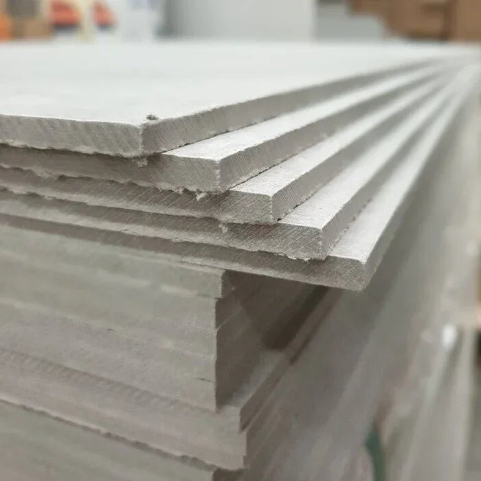
The STS NoMorePly full-size 2.4 m × 1.2 m × 12 mm fibre-cement render carrier board is the storey-height substrate in our rendering cement boards range — sized for continuous stud-bay runs on timber-frame, steel-frame, and SIP-panel facades where minimising joint count across long wall runs matters more than handling weight. At 45 kg per board with 2.88 m² coverage, the format covers a full storey height in a single sheet on most UK domestic and mid-rise builds, with Euroclass A1 non-combustible classification, 12.46 MPa dry bending strength, and 1,650 N mean pull-through resistance at the screw. Manufactured to BS EN 12467:2016 + A1:2016. Trade collection or next-day UK dispatch from our Southampton warehouse.
What the STS Full-Size Render Carrier Board Does on Storey-Height Elevations
The 2,400 × 1,200 × 12 mm carrier board is the standard render-substrate format on UK timber-frame, steel-frame, and SIP construction — sized to cover a full storey height in a single sheet across most domestic and mid-rise wall heights. Density holds at 1.28 g/cm³, bending strength is rated at 12.46 MPa dry and 12.91 MPa after warm-water saturation, and pull-through resistance averages 1,650 N at the screw. The saturated bending value is the one to read carefully: 12.91 MPa after warm-water testing confirms the board does not soften when wetted by basecoat application or driving rain across the working life of the facade.
The 2.88 m² coverage per board is the structural reason this format dominates full-elevation work. Every joint on a render carrier substrate is a basecoat reinforcement task — mesh bedded into a fresh flexible adhesive bead, staggered against the joints in adjacent rows, primed across the taped line to equalise suction against the unjointed face. On a 30 m² gable elevation, switching from half-size to full-size boards drops joint linear metres by more than half, and that proportion translates directly into basecoat reinforcement labour saved.
What Makes the 2.4 × 1.2 m Carrier Board Worth Specifying on Full Elevations
- Lowest joint count per square metre in the range: 2.88 m² coverage per board is the practical SKU choice for continuous stud-bay runs where every joint becomes a mesh-embedment task — full sheets across a storey-height elevation drop reinforcement labour proportionally against half-size board count.
- Euroclass A1 non-combustible: tested under EN 13501-1, EN ISO 1182, and EN ISO 1716, supporting facade specifications where the project fire strategy specifies a non-combustible carrier behind the render — subject to design verification under current Approved Document B guidance.
- Heavy-duty fixing performance: 1,650 N mean pull-through and 840 N pull-out values give meaningful headroom for direct fixing of sills, oversills, ancillary trims, and lighter cabinet work to the board face without falling back to separate substrate-mounted brackets.
- Dimensionally stable across moisture cycles: 0.16% linear variation under moisture loading keeps joints tight after basecoat application, reducing the reflective cracking risk that drives most post-handover remediation on rendered facades.
- Full BS EN 12467 compliance: Category A, Class 2 mechanical (MOR) classification with verified freeze-thaw, heat-rain, warm-water, and soak-dry durability — the test scope that NHBC and BBA-certified system specifications expect on rendered facade substrates.
- Render-ready face when primed: primed water impermeability shows no damp patch after 192 hours of contact testing, giving basecoat consistent suction across the full panel area and a uniform cure that detail-area work cannot match purely on geometry grounds.
Technical Specifications — STS Full-Size Render Carrier Board Data
| Property | Value |
|---|---|
| Dimensions | 2,400 × 1,200 × 12 mm |
| Coverage per board | 2.88 m² |
| Board weight | 45 kg (±2% tolerance) |
| Density | 1.28 g/cm³ |
| Bending strength (dry / saturated) | 12.46 MPa / 12.91 MPa |
| Compression strength | 14.42 MPa |
| Linear variation with moisture | 0.16% |
| Thermal conductivity (λ) | 0.241 W/mK |
| Reaction to fire | Euroclass A1 — non-combustible |
| Fire test references | EN 13501-1 · EN ISO 1182 · EN ISO 1716 |
| Pull-through resistance (mean) | 1,650 N at screw |
| Pull-out resistance (mean) | 840 N |
| Water impermeability (primed face) | No damp patch after 192 hours |
| Manufacturing standard | BS EN 12467:2016 + A1:2016 (Category A, Class 2 MOR) |
| Matched fixing | STS 38 mm Ruspert-coated screws (sold separately) |
| Typical screw count per board | 30–35 screws on stud framing at 600 mm centres |
How the Full-Size Carrier Board Installs on Continuous Stud-Bay Runs
The full-size carrier board fixes directly to timber or light-gauge steel framing behind, ahead of any render layers, using the matched STS 38 mm Ruspert-coated screws at 200 mm centres on board perimeters and 300 mm in the field — typically 30–35 screws per 2.88 m² board on stud framing at 600 mm centres. Drive flush with the board face; flush is the target, since the published 1,650 N pull-through value depends on the screw head bearing properly against an undamaged board face rather than fractured material around an over-driven head.
Leave a 3–4 mm gap between boards, fill with a flexible cementitious adhesive, and embed reinforcement mesh while the adhesive is still wet — with mesh overlapped per the fibreglass mesh overlap guide across every joint. Stagger joints between adjacent rows so no four boards meet at a single point, since that geometry is where reflective cracking concentrates if the joints align. Prime the full surface with a quartz primer before render application to equalise suction between the board face and the basecoated joint lines. Where the carrier sits within an EWI build-up, the assembly may also require mechanical anchors back to the structural wall, and the insulation fixing accessories range covers the matched anchors and spiral fixings. For the complete installation sequence with primer selection, joint treatment, and thin-coat finish integration, our cement boards for rendering guide walks through the worked process.
Installation Notes — Two-Person Handling, Joint Stagger, Pull-Through Headroom
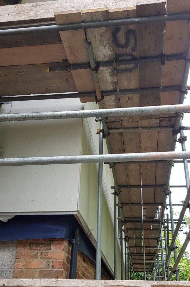
For the best result, treat the 45 kg weight as the planning constraint that drives lift logistics, not as an obstacle to work around at the panel. Pre-cut boards at ground level wherever the geometry permits — measuring at height adds risk and time, and a cutting station set up next to the scaffold loading bay turns over boards faster than the alternative of carrying full sheets up for measuring. Two-person handling on scaffold is the realistic working assumption above first-lift, and a third pair of hands at scaffold level on the receiving end accelerates the placement step on storey-height runs.
The 1,650 N pull-through and 840 N pull-out values are the structural reason this board carries ancillary load reliably — oversill brackets, downpipe clips, light cabinet work, and similar trim fixings can be attached directly to the board face rather than requiring a separate substrate-mounted bracket detail behind. That headroom is meaningful on facades where the trim schedule is dense around openings, and it is a working advantage that the smaller carrier-board formats do not always deliver because the available board area for fixing is more constrained.
How the Full-Size Board Compares to the Half-Size 1.2 × 0.8 m Format
Both formats share the same fibre-cement composition, the same EN 12467 mechanical class, the same 12 mm thickness, and the same Euroclass A1 fire classification — the specification narrative on the project compliance dossier is identical. The choice between them is a handling, joint-count, and cut-yield decision driven by the geometry of each area on the elevation.
| Format | Coverage · Weight | Best For |
|---|---|---|
| Full-size (this product) | 2.88 m² · 45 kg | Storey-height panels, continuous stud-bay runs · two-person handling · lowest joint count per m² |
| Half-size 1.2 × 0.8 m | 0.96 m² · 15.8 kg | Reveals, dormers, soffit returns · single-person handling · lower cut-waste on detail areas |
On most domestic and mid-rise facades, a planned mix between the two formats is the most efficient ordering pattern — full sheets carry the main wall areas where continuous bays reward larger boards and fewer joints, half-size carries the reveals and detail work where small geometry rewards less cut-waste. The same STS 38 mm Ruspert-coated screw fixes both formats, so the fixing schedule consolidates onto a single SKU even when the board mix splits.
What UK Installers Do Differently With the Full-Size Render Board
- Grade off-cuts at the cutting station, not at the skip: off-cuts from full sheets above roughly 0.4 m² are usually useful for reveal panels, sill returns, and verge detail — building a graded off-cut stack next to the cutting station captures that material before it ends up in the skip and reduces the half-size board count the project actually needs to order.
- Plan scaffold lifts to handle the 45 kg drop: a typical storey-height elevation runs to several full-sheet lifts in sequence, and a two-board buffer at scaffold level keeps the placement crew working without runs back to ground stock. Lift sequencing planned at scaffold-design stage avoids the awkward midway pause that emerges if board count exceeds lift capacity on a single delivery.
- Use the pull-through headroom for trim fixings: the 1,650 N mean pull-through value gives meaningful capacity for direct ancillary fixing — oversill brackets, downpipe clips, and lighter cabinet work can go straight into the board face without a separate substrate-mounted bracket detail, simplifying the trim schedule and reducing the fixing-pattern coordination work around openings.
- Stagger joints by a clear board-width step, not half a board: on storey-height runs, a half-board stagger between adjacent rows produces a joint geometry that reads visually as a near-alignment from the elevation view. A clear board-width offset between rows breaks the joint line cleanly and is the geometry that reflective-crack mitigation actually depends on.
- Prime the field before priming the joints: a uniform primer pass across the unjointed board face equalises the bulk of the suction differential, and a second pass concentrated on taped joints brings the joint suction up to match. Working the field first lets the joints sit and absorb properly before the second pass, rather than fighting differential cure across the whole panel from a single rushed application.
Is the Full-Size Render Carrier Board Right for Your Project?
- Storey-height timber-frame or steel-frame walls: the right format — full sheets cover continuous stud-bay runs with the lowest joint count per square metre in the range, dropping basecoat reinforcement labour against the half-size alternative on long wall runs.
- Fire-strategy-driven facade specifications: the Euroclass A1 classification supports facade build-ups where the project fire strategy specifies a non-combustible carrier, subject to design verification under current Approved Document B guidance.
- Mid-rise commercial and residential facades: the BS EN 12467 Category A, Class 2 MOR classification with verified freeze-thaw and heat-rain durability suits the test scope NHBC and BBA-certified system specifications expect on rendered facades at mid-rise scale.
- Reveals, dormers, and soffit returns: consider the half-size 1.2 × 0.8 m board — lower cut-waste on detail areas and single-person handling at height where two-person lifting of a 45 kg sheet would be awkward.
- EWI on solid masonry walls: a carrier board is rarely needed where render goes directly onto basecoated insulation over solid masonry — this range applies to frame construction where the carrier substrate is part of the build-up.
FAQ — STS Full-Size Render Carrier Board Coverage, Compatibility, Ordering
Is the 12 mm board genuinely Class A1 non-combustible?
Yes — tested to EN 13501-1 with supporting EN ISO 1182 and EN ISO 1716 results, the board is classified Euroclass A1 non-combustible. That suits facade build-ups where the project fire strategy specifies non-combustible materials behind the render finish, subject to design verification under current Approved Document B guidance. The classification appears on the manufacturer's A1 reaction-to-fire certificate linked in the technical documentation below.
How many screws are needed per board?
Typical fixing pattern is 200 mm centres on board perimeters and 300 mm in the field, giving roughly 30–35 screws per 2.88 m² sheet on stud framing at 600 mm stud centres. A 250-piece box of the matched STS 38 mm Ruspert-coated screws covers approximately 7 full-size boards on this fixing schedule. Always cross-reference the system designer's spacing schedule for the specific facade build-up.
Do I need to prime before rendering?
Yes. A quartz-loaded primer equalises suction between the board face and the basecoated joint lines, which delivers a more uniform render finish across the panel. The TDS confirms that primed water impermeability remains intact after 192 hours of contact testing, so the primed surface holds its working properties across the long programme duration typical of storey-height EWI work.
How heavy is one sheet, and what handling is required?
45 kg per board, with a ±2% manufacturing tolerance. Two-person handling is the realistic working assumption on scaffold, especially above first-lift level. Pre-cutting at ground level wherever the geometry permits speeds the install and keeps measuring at height to a minimum — and a buffer of two boards at scaffold level on storey-height runs lets the placement crew work without runs back to ground stock between lifts.
What can be fixed directly into the board face?
The 1,650 N mean pull-through and 840 N pull-out values support direct fixing of lighter ancillary trim — oversill brackets, downpipe clips, light cabinet work, and similar — into the board face without a separate substrate-mounted bracket detail behind. Heavier loads (kitchen wall units, structural rails, supporting brackets for cladding) should be fixed back to the structural framing behind via penetrating fixings, since the pull-through values cover the board itself rather than load transfer into the wall structure.
Can this format be used for internal applications?
Yes. The Class A1 fire rating and primed water impermeability suit internal wet rooms, shower enclosures, and tile-backer applications, and the 2.88 m² coverage covers wet-room walls with fewer joints than the half-size format. Tanking and waterproofing membrane requirements should be confirmed against the manufacturer's current recommendations for the specific wet-room use case.
Is the board suitable for mid-rise commercial facades?
The BS EN 12467 Category A, Class 2 MOR classification with verified freeze-thaw, heat-rain, warm-water, and soak-dry durability suits the test scope that NHBC and BBA-certified system specifications expect on mid-rise rendered facades. Project-specific suitability rests on the system designer's full specification — including fire strategy, wind-load calculations, and the certified system the board sits within — so confirm against the project specification before commitment on mid-rise builds.
Technical Documentation — STS Full-Size Carrier Board TDS and Fire Classification