


Description
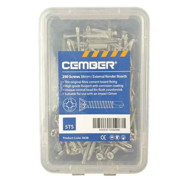
Render board screws fix fibre cement board to a timber batten framework and pull flush under the basecoat. This box holds 250 of the 3.95 mm by 38 mm Ruspert-coated fastener, enough for roughly nine full 2400 x 1200 mm sheets at 600 mm batten centres.
Where Render Board Screws Fit on a Cement Board Facade
These render board screws are the 3.95 mm by 38 mm fastener STS specifies for fixing fibre cement sheet to a timber framework, driven flush before basecoat and mesh. The datasheet is explicit that the screw is designed for a 12 mm board and is also great for use with any other fibre cement sheet material, which is why Renders World keeps it in the rendering cement boards range beside the 12.5 mm sheets stocked here.
The board itself is specified for timber frame, lightweight steel frame and modular or offsite construction, and it always sits on battens over a vented cavity. The screw's job is the board-to-batten connection in that build-up, so the settings it covers follow the batten, not the wall behind it.
- Timber-framed and offsite construction: boards fixed to vertical battens of minimum 25 x 60 mm at 600 mm centres, or 400 mm centres where the elevation carries higher wind load or exposure.
- Over-boarding an existing substrate: the same schedule applies, with the battens themselves fixed firmly through to the structural frame behind.
- SIP panels: the carrier board guide treats the outer OSB layer as structural enough to take the batten framework directly, over a breather membrane, battened out vertically at 400 mm or 600 mm centres.
Light-gauge steel framing is specified separately. The carrier board guide names a 4.8 x 38 mm wingtip self-drilling screw there, not the 3.95 mm timber screw in this box.
Why Installers Specify the Ruspert-Coated 38 mm Board Screw
- A coating built in layers, not plated on: the datasheet describes a free zinc layer in contact with the base metal giving sacrificial protection, a chemical conversion layer above it, and a baked ceramic topcoat acting as the physical barrier. The conversion layer is what stops the ceramic and zinc separating under abrasion.
- Classified corrosion performance: Ruspert grades are set by hours in neutral salt spray before red rust appears, and all STS Ruspert products are stated as R1000 or R1500. Specify against the R1000 floor — 1000 hours to red rust, comparable to a class 3 screw for mild to moderate industrial or marine exposure.
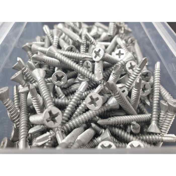
- Conical head for a flush countersink: the 7 mm head pulls level with the board face, leaving the flat plane that basecoat and mesh need so no head reads through the finished topcoat.
The ceramic layer is described as protecting the zinc and the substrate from both acid and alkaline attack, which is the exposure a fastener meets in the damp, high-pH zone behind a cement basecoat. The same sheet lists compatibility with treated hardwood and softwood, and confirms the screw suits an impact driver — which is what most installers reach for.
Technical Specification From the STS Datasheet
| Property | Value |
|---|---|
| Manufacturer product name | External Render Board Screw |
| STS product SKU | 5638 |
| Length | 38 mm |
| Major diameter, threads | 3.95 mm |
| Head style | Flat, conical countersink |
| Head diameter | 7 mm |
| Drive | Phillips |
| Drilling width | 3.52 mm |
| Recess | 2.8 mm |
| Shank diameter | 2.68 mm |
| EAN barcode | 5055377256388 |
| Coating | Ruspert multi-layer, ceramic topcoat |
| Corrosion grade, STS Ruspert range | R1000 or R1500 |
| Board compatibility | 12 mm board, and any other fibre cement sheet material |
| Box quantity | 250 |
Every figure above is read off the STS datasheet for SKU 5638, dated 14 February 2024. That sheet sets nine labels against nine values in the same order, so the recess depth and the shank diameter belong to this screw rather than to a neighbouring line.
How to Install: Batten Centres, Edge Distance and Fixing Counts
Render board screws are set out from the board guide rather than from a rule of thumb, and the counts are quoted per full sheet at each batten spacing. Setting the schedule out before the first board goes up is what keeps the elevation consistent from ground to eaves.
| Batten centres | Fixings per 2400 x 1200 mm sheet | Orientation |
|---|---|---|
| 400 mm | 28 | Horizontal or vertical |
| 600 mm | 27 | Horizontal |
Edge distance follows the board, not the screw. On the EASYBOARD sheets stocked here, the Euroform data sheet is specific: the first fixing in from a corner, horizontally and vertically, must be 40 mm in from the edge, and a minimum 3 mm gap is left at all joints to take up humidity movement. Board width is not taken below 600 mm, four-way joints are avoided, and sheets are laid in brick bond.
The 20 mm edge distance often quoted with this screw is the STS figure for its own 12 mm carrier board, where STS also report testing successfully at 15 mm. It is the right number on that board; here the figure to set out from is the Euroform 40 mm, so check whose sheet a figure came from first.
Set the depth stop on the driver against an offcut before starting the elevation proper, and every head lands at the same plane across the wall. Fill the joints with the basecoat mix where render follows soon after boarding — the same EPS adhesives basecoats range supplies the mesh-embedding coat that goes over the fixed boards, ahead of primer and the thin-coat silicone render finish the guide illustrates as the typical build-up.
Two cavity details from the carrier board guide are worth carrying into the specification, because one of them changes by nation. The cavity must be vented top and bottom with a minimum 15 mm airflow gap, and while a 60 x 25 mm batten satisfies England and Wales, the guide sets a minimum 50 mm cavity depth for Scotland, Northern Ireland and the Republic of Ireland. The cement board installation guide works through the full sequence, and the timber frame moisture and airtightness notes cover why that vented cavity earns its place.
How Many Boxes to Order for Your Board Count
Because the fixing count per sheet is published, a box of render board screws converts cleanly into board area. Both figures use the full 2400 x 1200 mm sheet at 2.88 m² and round down to whole sheets, so the last board on the pallet is never short.
- At 600 mm centres: 250 ÷ 27 fixings per sheet = 9.2, taken down to 9 whole sheets; 9 x 2.88 m² = 25.9 m² of board per box.
- At 400 mm centres: 250 ÷ 28 = 8.9, taken down to 8 whole sheets; 8 x 2.88 m² = 23.0 m² per box.
- Half-size boards: the guide publishes fixing counts only for the full sheet, so quantities for the 1200 x 800 mm board are set on site from the same perimeter and intermediate pattern rather than from a published figure.
Add a box for offcuts and replacements on any elevation with a lot of openings, since cut pieces need their own perimeter fixings. Renders World stocks the box beside the boards it belongs to.
Ruspert or Zinc-Plated: Checking the Right 38 mm Screw
Two 38 mm screws sit close together under the STS render board screws name, and on a shelf the boxes look similar. Renders World stocks only the external one. The external screw is SKU 5638, Ruspert coated, 250 to a box; the internal fibre-cement board screw is SKU 5647, zinc plated, 200 to a box, a separate product for internal work. Count the box and check the coating — that is the whole check. Insulation is a different job again: EPS, graphite EPS and mineral wool take mechanical plugs and base tracks from the insulation fixing accessories range.
- External render on a cement board, timber framework: these render board screws. Ruspert coating, conical flush head, and the 3.95 x 38 mm size the guide names for timber.
- Light-gauge steel framing: specify the 4.8 x 38 mm wingtip type the guide calls for on SFS instead, and confirm the fastener is stainless or suitably treated for external use.
- Internal wet-room and tile-backer work: that is the zinc-plated 200-piece screw, which this shop does not stock. This box is the external one.
Ready to order: match one box to nine full sheets at 600 mm centres, and put the 2400 x 1200 mm cement board on the same delivery so the fixings arrive with the boards they belong to.
FAQ — Fixing Counts, Frame Type and Coating
How many screws does a full board take?
The guide gives 27 fixings per 2400 x 1200 mm sheet on battens at 600 mm centres, and 28 per sheet at 400 mm centres. A 250-piece box of render board screws therefore covers nine full sheets at the wider spacing and eight at the closer one, once rounded down to whole boards.
Can these screws fix boards to steel framing?
For all SFS framing the board guide recommends a 4.8 x 38 mm self-drilling, self-countersinking wingtip fixing rather than the 3.95 mm timber screw, with the fastener stainless or suitably treated and approved for external use. Confirming the frame type at survey keeps the right fastener in the specification from the start.
How close to a board edge can the screws go?
It depends whose board is being fixed. On the EASYBOARD sheets stocked here, Euroform require the first fixing in from a corner to be 40 mm in from the edge, horizontally and vertically, with a minimum 3 mm gap at every joint. The 20 mm figure often quoted with this screw belongs to the STS 12 mm carrier board, with 15 mm reported as tested; on an EASYBOARD elevation the number to set out from is 40 mm.
What corrosion grade does the Ruspert coating carry?
All STS products with Ruspert coating are stated as R1000 or R1500 grade, classified by hours in neutral salt spray before red rust appears. An R1000 coating also conforms to 12–15 cycles of the DIN 50018 sulphur dioxide gas corrosion test, comparable to a class 3 screw for mild to moderate industrial or marine environments. The datasheet does not tie SKU 5638 to one of the two grades, so specify against R1000 as the floor.
How should boxes be stored on site?
Keep boxes closed and dry in the compound, on a shelf rather than the floor. It is ordinary good practice with any coated fastener and takes nothing more than a lid and a dry shelf.
Technical Documentation