RENDERING CEMENT BOARDS
3 products
Showing 1 - 3 of 3 products
Renders World supplies rendering cement boards to UK render contractors as a three-part substrate package — two board formats and the matched screw — and they form the carrier layer of the thin coat render systems.
Which UK Builds Need a Render Carrier Board
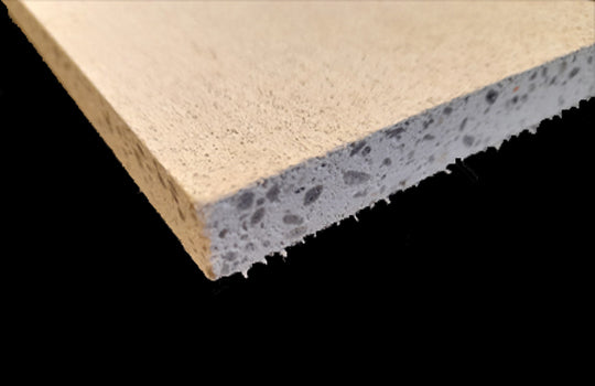
Rendering cement boards carry thin-coat render on framed construction, and the Easyboard sheet stocked here is manufactured to BS EN 12467:2012+A2:2018 at 39.6 kg per 2,400 × 1,200 mm board — the substrate timber frame, light steel frame and SIP facades need.
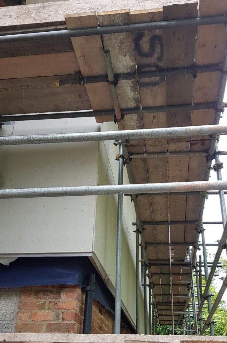
The cavity governs all three: a carrier board requires a ventilated void behind it, open top and bottom, with a minimum 15 mm airflow gap where the boarding would otherwise finish flush with the wall below.
- Timber frame: breather membrane first, then vertical battens — the orientation carrier board guides recommend so the cavity vents.
- Light steel frame: SFS work takes a 4.8 × 38 mm wingtip screw rather than the 3.95 × 38 mm timber fixing.
- SIP panels: no internal studwork, so battens fix straight to the outer OSB at 400 or 600 mm centres, and moisture sequencing sits in the timber frame moisture and airtightness guide.
Why Specifiers Put Fibre Cement Behind a Thin-Coat Facade
- A declared durability class: Category B, Class 1 to BS EN 12467 — the external-exposure classification a system designer asks to see, carried by a UKCA mark to BS EN 12467:2012+A2:2018.
- Strength that survives a wet spell: at least 4 MPa average wet bending strength declared after saturation, so the sheet keeps its working strength through site exposure. Pull-through and pull-out values are not published for this board, so take rails back to the frame rather than assuming the face will hold them.
- No thermal pretence: 0.22 W/mK, so at 12.5 mm the sheet is worth almost nothing in a U-value — the insulation layer does that work.
One thing this page will not do is borrow a figure from a neighbouring board. The reaction-to-fire class here is declared for the sheet itself: A1, non-combustible, to BS EN 13501-1. It is a board-level class, and on a rendered facade the class that governs belongs to the whole build-up, so confirm it against the project fire strategy under current Approved Document B guidance.
The two density figures are the same sheet in two states, not a contradiction: 900 kg/m³ apparent for the dry board and 1,225 kg/m³ saturated once it has taken up water. Where a calculation turns on mass — dead load on the batten framework, or a scaffold loading schedule after a wet week — work to the saturated figure.
Choose Your Board Format and Fixing Pack
The two formats differ in handling, not in performance: both are 12.5 mm, both carry the same classes, and both take the same screw. The full sheet covers 2.88 m² and is the one to plan storey-height runs around; the half sheet covers 0.96 m² and earns its place at reveals, dormers and infill panels, where a full board would be mostly offcut. Current prices for both sit on the product pages below.
| Your Project | Best System | Standout Spec |
|---|---|---|
| Storey-height wall runs | Easyboard 2400 × 1200 × 12.5 mm | 2.88 m² · 39.6 kg · A1 non-combustible |
| Reveals, dormers, infill panels | Easyboard 1200 × 800 × 12.5 mm | 0.96 m² · 13.2 kg · same board, half sheet |
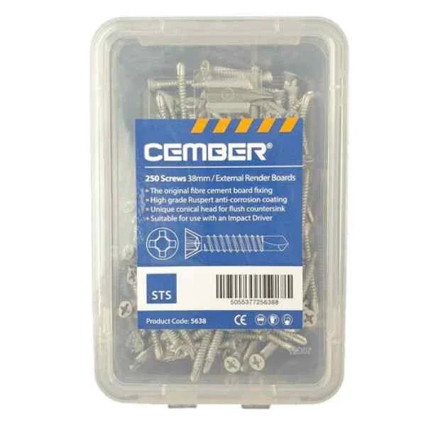
| Fixing either format to the frame | Render board screws 38 mm | 250 per box · 3.95 × 38 mm · Ruspert coated |
Delivery is quoted per order: in-stock lines process the same day, pallets up to 1,200 kg move next day or two business days on the economy option, and local delivery in the company van is free on larger orders within 15 miles of the Southampton base. Shop prices are shown without VAT, which is added at checkout.
How to Fit the Boards, Then Render Over Them
The build sequence runs frame, battens, board, primer, basecoat with mesh embedded, then render finish — and the fixing schedule is a count per sheet rather than a spacing to eyeball.
- Batten out: vertical battens at 600 mm centres, or 400 mm on exposed high wind-load elevations, minimum 60 × 25 mm. Scotland, Northern Ireland and the Republic of Ireland work to a 50 mm minimum cavity depth.
- Set out: a 3–5 mm gap on all sides, joints staggered, and no board joint running out from a window or door edge — cut around the opening onto a 25 × 60 mm batten.
- Fix: 3.95 × 38 mm self-drilling, self-countersinking screws into timber, 20 mm in from edges, at 27 per full sheet on 600 mm battens and 28 on 400 mm battens.
- Reinforce: prime, then bed mesh into the basecoat across every joint, doubling it at opening corners as most render manufacturers ask.
Movement joints belong in the design: Carrier board guides put them at 15 m maximum spans or on the substrate's own joints, the gap itself no wider than 25 mm, agreed with the render manufacturer, architect or building control. The worked sequence sits in the cement board rendering guide, the priming coat in our exterior render primers, the bedding layer in the EPS adhesives basecoats range, and reveal sequencing in the window and door detailing guide.
Site Notes From UK Render Crews
Three things a carrier board guide answers that a takeoff sheet usually does not.
- The two-month rule beats a tarpaulin: boards stand exposed for up to six months, but where render is more than two months off, carrier board guides want PU adhesive between the boards at install, or external-grade filler and weatherproof tape on the joints later.
- Buy screws by sheet count: 250 ÷ 27 fixings per sheet = 9 boards per box, so one box per nine boards plus a spare covers edge replacements.
- Plan the drop: a 45 kg sheet sits past the 25 kg parcel band, so boards arrive on a pallet, kerbside, wrapped but not weatherproof.
Deciding Whether the Range Suits Your Build-Up
- Framed new build with render: the core case — board, batten and matched screw give the system a plane that holds still.
- Thin-coat finish to follow: Carrier board guides advise a flexible system over sand and cement, which is where thin-coat silicone render takes the elevation on.
- Insulation in the same build-up: our insulation fixing accessories cover the plugs, anchors and base tracks.
- Warranty-inspected housing: board fixing and joint detailing are inspection points, covered in the NHBC render detailing guide.
- Solid masonry: a different route — render onto primed masonry needs no carrier board at all.
Renders World stocks all three lines together: take the 2400 × 1200 mm board for the open elevations and add the half sheet for detail areas.
FAQ — Cavity Depth, Fixing Counts and Ordering
How many screws does one board take?
Twenty-seven per 2,400 × 1,200 mm sheet on battens at 600 mm centres, or 28 on 400 mm centres. A 250-piece box of 38 mm render board screws therefore covers nine full sheets.
How long can the boards stay exposed before rendering?
The carrier board guides give up to six months, and the Easyboard data sheet prints no exposure window at all — so confirm it against the sheet supplied with your batch rather than planning around a remembered figure. Past two months, carrier board guides ask for PU adhesive between boards at install, or an external-grade joint filler and weatherproof tape afterwards, and the boards must be dry, dust-free and undamaged before render goes on.
Can sand and cement render go over these boards?
Carrier board guides recommend a flexible thin-coat silicone system instead. Cement sets completely solid, and a joint that moves slightly is better bridged by a flexible finish over mesh — which is why the reinforced thin-coat build-up is the specification here.
Does the required cavity depth differ across the UK?
Yes. England and Wales work to the batten depth, commonly 60 × 25 mm, while Scotland, Northern Ireland and the Republic of Ireland take a 50 mm minimum cavity depth. Confirm the membrane and cavity with building control or the project engineer.