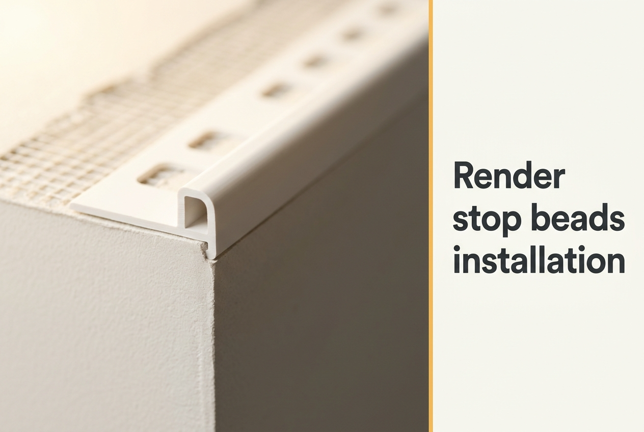
At 3–15 mm depths matched to render system thickness, PVC render stop beads define every clean, straight edge where a render coat terminates — at soffit lines, window jambs, door frames, and any junction where the render meets a different material. Fitting them correctly is one of the most consequential decisions a UK contractor makes during the render programme, because a poorly installed stop bead produces edge cracking and water ingress that emerges within the first winter and costs many times the bead's £2-per-metre material price to remedy after the system is complete. This guide covers the full stop bead installation process for the render stop beads range at Renders World — depth selection, fixing sequence, mesh-wing embedment, render-pass discipline, and the float-stroke habit that causes most edge failures on British sites. For the wider context of how stop beads sit within profile sequencing at openings, the render detailing around windows and doors guide covers the full junction discipline that this installation method sits inside.
Why Stop Bead Installation Discipline Decides Whether a Render Edge Lasts
Without a stop bead, a render coat terminates in a feathered edge that is physically weak and difficult to waterproof. The feathered edge thins to almost nothing at the boundary, so any movement in the substrate — thermal expansion, wind-load flex, or minor settlement — can propagate a crack right along the line where the render meets the adjacent material. Over a typical UK winter, where a west-facing elevation can see daily temperature swings of twenty to twenty-five degrees between a cold overnight frost and an afternoon of direct low sun, that movement is not a remote risk — it is a routine event.
A correctly installed PVC stop bead solves the problem in two ways simultaneously. The rigid profile acts as a depth gauge during render application, keeping the coat at consistent thickness right up to its edge and eliminating the thinning that creates vulnerability. The nose of the bead then forms a mechanical separation between the render and the adjacent material, so differential thermal movement between the two materials cannot transfer stress directly into the render face. Both functions are delivered by a single low-cost component that takes under two minutes per linear metre to install — and the installation discipline is what decides whether those two functions actually work, or whether the bead becomes a visible defect line itself.
Choosing the Right Stop Bead Depth Before the Adhesive Goes Out
The depth decision is the first installation step, made before any adhesive is mixed and before any datum lines are marked. Choose a bead that matches the finished thickness of the render system at the termination edge. If the bead is shallower than the render layer, the nose buries inside the coat and the render overshoots the profile — effectively recreating the same feathered termination the bead was installed to prevent. If the bead is too deep, the nose stands proud of the finished surface, creating a shadow line that traps dirt and invites mechanical damage at every passing knock.
| Render System | Build-Up Thickness | Recommended Stop Bead | Length |
|---|---|---|---|
| Thin-coat silicone or silicate-silicone | 4–10 mm | 3 mm or 6 mm PVC with mesh | 2.5 m |
| Acrylic thin-coat over masonry | 4–8 mm | 6 mm PVC no mesh | 2.5 m |
| EWI basecoat + thin-coat topcoat | 6–10 mm (render only) | 6 mm PVC with mesh | 2.5 m |
| Machine-applied monocouche | 12–15 mm | 10 mm PVC no mesh | 2.5 m |
| Traditional sand-and-cement (2-coat) | 14–18 mm | 15 mm PVC no mesh | 2.5 m |
The single most-specified UK profile across both new-build and retrofit work is the 6 mm mesh-wing variant, because it covers the standard EWI thin-coat build-up that dominates current trade installations. For the full bead-selection logic across stop, corner, and bellcast profiles in one decision matrix, the render bead selection guide sets out which profile suits which junction type across the whole silo.
Step-by-Step — Installing a Stop Bead on a UK Render System
Stop bead installation is a precision task that has to be planned into the render sequence from the start. On EWI systems, the insulation boards and mechanical fixings must already be in place and the adhesive basecoat must have reached initial set before any beads are fixed. The same eight-step sequence applies whether the system is EWI thin-coat or direct-to-masonry rendering, with the substrate preparation step adjusting to suit the material being primed.
- Mark termination lines with a laser level or chalk line. Stop beads must be perfectly plumb on vertical runs and perfectly level on horizontal ones — any deviation will read as a wavering line through the finished render coat. Strike the datum lines first, before mixing any adhesive, and verify with a spirit level at 600 mm intervals.
- Prepare the substrate at the fixing zone. Remove loose mortar, paint, or contamination from the strip where the bead wing will sit. On block or brick substrates, key any painted or sealed surface with coarse sandpaper. The substrate must be clean, sound, and free of frost. On EWI build-ups, the basecoat reinforcement layer must have reached initial set — typically twenty-four hours at UK ambient temperatures above five degrees.
- Apply a continuous bed of adhesive basecoat mortar. Trowel a 6–8 mm bed of system-compatible EPS adhesive or basecoat along the marked line. Use a continuous bed rather than isolated spot dabs — spot fixing leaves voids behind the bead where moisture accumulates and freeze-thaw cycling eventually forces the bead away from the wall.
- Press the bead into position and align to the datum. Bed the bead wing firmly into the adhesive, pressing uniformly along its full length. Check for plumb or level immediately. The bead can be adjusted in the mortar for ten to fifteen minutes before the adhesive begins to set. Do not use steel nails or screws to hold the bead on EWI systems — mechanical fixings through insulation boards create thermal bridges and moisture paths into the substrate.
- Join consecutive lengths cleanly. Butt adjacent bead lengths tightly with no gap wider than 1 mm. Where the bead has a mesh wing, overlap the mesh wings of consecutive beads by a minimum of 100 mm and embed the overlap zone into fresh mortar. Stagger bead joints at least 300 mm away from any window or door corner, where structural movement in the frame concentrates higher stress.
- Allow full initial set before rendering. Do not apply render over a freshly fixed bead. Allow the adhesive bed to reach firm initial set — typically twenty-four hours in standard UK conditions — before any render coat goes on. Rendering too soon distorts the bead profile, compromises the adhesive bond, and reveals itself as a wavy termination line through the finished face.
- Render flush to the bead nose. Apply the render coat up to the nose of the profile so the finished surface is flush with — not overhanging — the bead edge. Run the trowel or float tight to the nose on the final pass. If any render creeps past the nose onto the face of the profile, clean it off immediately with a damp brush before it cures.
- Seal the junction with a low-modulus sealant. Once the render has cured, apply a 2–3 mm bead of low-modulus UV-stable silicone or polyurethane sealant into the gap between the stop bead nose and the adjacent frame, board, or cladding material. This sealant joint absorbs differential thermal movement between the render system and the adjacent material without cracking the render face, and it provides the primary waterproof seal at the termination point.
Mesh-Wing Embedment — How the Stop Bead Ties Into the Reinforcement Layer
On every EWI and thin-coat render system, the mesh wing of the stop bead is what ties the termination edge into the facade's continuous tensile network. The mesh wing must overlap the main fibreglass reinforcement sheet by a minimum of 100 mm, embedded into a single continuous bed of basecoat mortar. The overlap zone is what carries tensile stress across the joint between bead and field mesh — without it, the termination edge becomes a discontinuity where stress concentrations initiate the cracks that subsequently propagate into the render face.
The overlap rule is non-negotiable on coastal, gable-end, or high-exposure elevations where temperature swings are larger. On more demanding exposures, increasing the overlap to 150 mm gives a reserve margin against the larger thermal movement those walls experience. The same 100 mm overlap rule applies across both the bead-to-field-mesh junction and the field-to-field mesh overlaps elsewhere on the facade, so the dimension stays consistent across every joint in the reinforcement layer.
Common Stop Bead Failures and the Float-Pass Habit That Causes Most of Them
The single most frequent stop bead failure on UK sites is wet render overrunning the plastic nose of the bead during the final float finish. When a contractor works the float across the termination zone at a slight angle, the trailing edge of the float pushes render past the nose and onto the face of the profile. On a 3 mm or 6 mm thin-coat application, even a one-to-two-millimetre overshoot bridges the separation the bead was installed to create — and the consequence is the edge crack appearing during the first heating season as the rigid render-on-PVC patch flexes against the adjacent material.
The fix is straightforward and the discipline runs through five concrete habits.
- Float away from the nose, not toward it. Always finish the final render pass by drawing the float away from the bead nose toward the centre of the wall, not toward the edge. This single habit eliminates the overshoot mechanism completely.
- Pre-cut at ground level before scaffolding is busy. Stop beads at soffit terminations and above windows are easiest to measure and cut at ground level before the job starts. Measure each run individually — walls are rarely as uniform as a floor plan suggests — and label each bead so it goes in the right position without trimming on the scaffold.
- Do not mitre PVC at internal corners. At internal corners where two stop beads meet, run one bead past the corner and butt the second bead into its face, with a 2 mm sealant joint at the internal angle. Mitring PVC on internal corners creates a weak point that opens under thermal movement. Reserve mitre cuts for external corners only, where both beads meet cleanly at 45 degrees.
- Use the same adhesive as the rest of the render system. Mixed adhesives at the bead-fixing stage create differential stiffness and staining risk. Always use the system-compatible adhesive or basecoat specified for the rest of the build-up — do not substitute standard tile adhesive or grab adhesive, which are not alkali-resistant and can cause discolouration beneath light-coloured render finishes.
- Cut with a fine-tooth hacksaw, not snips. Snip cuts deform the PVC nose and leave a visible kink at the join; a fine-tooth hacksaw preserves the profile geometry and produces a butt joint that disappears under the basecoat.
How Stop Beads Coordinate With Bellcast, Corner Beads, and Window Details
Stop beads do not work in isolation — every render system needs a coherent set of profiles working together. The profile sequencing order across any elevation is bellcast first to establish the lower datum, stop beads second at frames and soffits, corner beads third at external wall angles. Installing stop beads before the bellcast risks a cold joint at the horizontal-to-vertical junction; installing corner beads before the stop beads makes the soffit and window-jamb runs harder to align cleanly to the corner datum.
Where a stop bead terminates at a junction with a bellcast bead — for instance, where a vertical termination at a window jamb reaches the head of the bellcast above a window — the standard detail is to cut the stop bead to finish 5 mm above the bellcast nose. This gap is then sealed with low-modulus sealant, creating a continuous waterproof line at the junction without two rigid PVC profiles bearing against each other. If the profiles are pushed hard against each other at this junction, differential thermal movement between the vertical and horizontal components will force one of them to buckle or separate from the adhesive bed within the first heating season.
For the corner bead installation discipline this sequencing depends on, the corner bead installation guide covers the third stage of the sequence in full detail. For the bellcast bead role at the DPC datum and above openings, the bellcast bead water-protection guide covers the first-stage profile that the stop beads then align against.
Key Takeaway: Fitting a correctly sized PVC stop bead at every render termination line prevents the three most common UK facade defects at edges — cracking, water ingress, and render de-bonding — at a material cost typically under £2 per linear metre. The float-pass habit that decides whether the bead works is to draw the float away from the nose, not toward it; the depth decision that decides whether the bead fits is matching the profile to the render system thickness; and the sequencing that decides whether the bead coordinates is bellcast first, stop bead second, corner bead third.
Order the Right Stop Bead Profile and Quantity for Your Project
Before ordering, identify three things: the render type, the required build-up thickness at the termination edge, and whether the bead must tie into a mesh-reinforced basecoat. With those three answers, the profile choice is a single lookup against the depth-selection table earlier in this guide. For a typical UK three-bedroom semi-detached property with four to six windows and two doors, the total stop bead requirement usually lands between 25 and 40 linear metres across all elevations, with the exact figure driven by window and door count and the complexity of any material transitions.
Measure each run individually — soffit lines, window jambs, door frames, material-change boundaries — divide the total by the standard 2.5 m bead length, round up to the next full length, and add ten to fifteen percent for cuts, joints, and waste. The full render stop beads range at Renders World ships next-day across the UK on stocked profiles, and the trade desk can confirm exact profile mix and quantity against elevation drawings for larger projects where junction count needs auditing before the order goes out.
Written by Mariusz Saja. Technically reviewed by Renders World Team. Last reviewed Jun 2026.
FAQ — Stop Bead Installation, Depth Selection, and Quantities
What is the difference between a stop bead and a corner bead?
A stop bead creates a clean, straight termination at the edge of a render coat — at a soffit line, a window frame, or a material boundary — where the render needs to end in a defined, protected line. It has no reinforcement function at structural corners. A corner bead is designed for external vertical arrises (the 90-degree external corners of walls and reveals) where it provides both a clean visual line and mechanical protection against impact damage. Both profile types are needed on a fully detailed facade and they are not interchangeable — each must be installed in the correct sequence as part of the complete profile system.
When do I need a mesh wing on my stop bead, and when can I use a no-mesh profile?
The mesh-wing variants are required on any application where the stop bead embeds into the reinforcement layer of an EWI or thin-coat render system. The mesh wing overlaps the main fibreglass reinforcement by 100 mm minimum, creating a continuous tensile layer right up to the termination edge. On direct-to-masonry rendering where no continuous mesh layer is present — traditional sand-and-cement and monocouche systems — a no-mesh bead at the matching depth is the right choice, and the heavier-nosed 10 mm and 15 mm profiles provide better mechanical edge protection for thicker render coats.
How many stop beads do I need for a typical UK house?
Measure every edge where the render terminates — window jambs, door frames, soffits, and material junctions — and total the lengths. Divide that total by the 2.5 m bead length, round up to the next full length so you are not left short on site, and add ten to fifteen percent for cuts, joints, and waste. On a typical UK three-bedroom semi-detached property with four to six windows and two doors, the total stop bead requirement usually falls between 25 and 40 linear metres across all elevations.
Can stop beads be installed in cold weather, and is there a minimum temperature?
PVC stop beads should not be installed when the substrate or ambient temperature is below five degrees Celsius. Below that threshold, the adhesive basecoat mortar fails to develop proper bond strength during curing, and PVC profiles become more brittle, increasing the risk of cracking if they are pressed firmly into cold mortar. The five-degree minimum that governs stop bead installation is the same threshold that governs render application generally, so on any properly managed UK site the two constraints are always addressed together.
What do I do if the render has already overrun the bead nose?
If the render is still wet, clean it off the face of the profile immediately with a damp brush before it cures. Working a small soft brush along the nose preserves the profile geometry without damaging the bead edge. If the render has already cured onto the face, score it carefully with a sharp knife along the nose line and remove the overshoot in small sections, then re-finish the render face with a damp sponge to restore the original surface texture. The fix is faster and cleaner if it happens before the render reaches initial set, which is why the float-away discipline matters more than recovery technique.
Can stop beads be painted to match the render colour?
PVC stop beads are supplied in white as standard and are UV-stable in that finish for the service life of the render system. Where a specific colour match is needed — for example, on a dark-rendered facade where a white nose line would read as a visible defect — the exposed nose can be over-painted with a compatible silicone masonry paint after the render has fully cured. Lightly abrade the PVC surface and ensure it is clean and dry before painting to achieve reliable adhesion under exterior exposure.
How much should the mesh wing overlap the main basecoat reinforcement?
The mesh wing must overlap the main fibreglass reinforcement sheet by a minimum of 100 mm at every joint. This 100 mm dimension maintains continuous tensile strength across the basecoat layer and prevents stress concentrations at the termination edge from initiating cracks in the topcoat. On more demanding exposures — coastal walls, exposed gables, or elevations with large temperature swings — an overlap of 150 mm gives additional reserve. The same 100 mm rule applies to field-to-field mesh overlaps across the rest of the basecoat reinforcement layer, keeping the tensile network continuous across every joint on the facade.