On any UK external wall insulation or thin-coat render facade, external corners take roughly 80% of the wall's accidental mechanical contact — and without a rigid reinforcing profile embedded into the basecoat at every arris, the render will crack at those corners within the first thermal cycle. Corner beads are one of the most critical yet frequently underestimated components in any render system: cheap to specify, decisive in the long-term performance of the facade. This guide from Renders World walks installers through the full process of selecting, cutting, embedding, and finishing render corner beads on UK building sites, covering PVC and aluminium profiles across standard, arched, and specialist applications.
Corner-bead detailing is one element of the broader profile-sequencing strategy across openings, beads, and reveals — the full sequence across windows, doors, and material transitions is covered in the render detailing around windows and doors guide, and the wider render beads and mesh hub sets out where corner profiles sit alongside stop, bellcast, and reinforcement products. This article focuses specifically on the corner-bead installation method.
Why Corner Beads Matter in EWI and Thin-Coat Render Systems
External corners are the most mechanically exposed points on any rendered facade. They absorb impacts from foot traffic, delivery vehicles, garden equipment, and even scaffolding during construction. Without a rigid reinforcing profile, the thin-coat render at these junctions cracks within the first thermal cycle, allowing moisture to penetrate the insulation layer behind. Corner beads solve this by providing a hard, straight edge that distributes impact forces across the mesh reinforcement layer rather than concentrating them at a single point. In the UK climate — where facades endure driving rain, frost, and sustained high humidity — this protection is not optional. It is a system requirement specified by every major EWI manufacturer and referenced in BS EN 13914-1 for external rendering, subject to current guidance.
Beyond impact resistance, corner beads serve an equally important aesthetic function. A perfectly plumb, sharp arris is the hallmark of professional rendering work — installers consistently report that clients, surveyors, and building inspectors all assess render quality by examining corners and reveals first. Investing five additional minutes per profile to ensure precise alignment pays dividends in final presentation and long-term durability across the full service life of the facade.
How to Choose the Right Corner Bead Profile for Your Application
The UK market offers several corner bead types, each suited to different project requirements. Understanding the distinctions before you arrive on site prevents costly material returns and ensures system compatibility throughout the facade. The decision framework breaks into three categories — PVC with integrated mesh, aluminium for high-impact zones, and arched profiles for curved geometry — with a clear preference order for each scenario.
PVC Corner Beads With Integrated Mesh
PVC profiles with factory-bonded alkali-resistant fibreglass mesh wings are the standard choice for EWI thin-coat render systems. The mesh wings — typically extending 100 mm to 150 mm on each side — embed directly into the basecoat layer, creating a continuous reinforcement zone around the corner. PVC is entirely corrosion-proof, which eliminates the rust-staining risk that affects galvanised steel beads in exposed coastal or high-rainfall UK locations. Products such as the corner PVC render bead with mesh 2.5 m are the most widely specified profile for domestic and light commercial EWI projects across England, Scotland, and Wales.
Aluminium Corner Beads for High-Impact Zones
Aluminium profiles offer greater rigidity than PVC, making them suitable for high-traffic commercial facades, school buildings, and ground-floor elevations where impact resistance is paramount. A standard aluminium corner bead 3.0 m provides a stiffer arris that resists deformation under heavy contact. The 3.0 m length also reduces the number of joints on a full-height wall, minimising potential crack-initiation points. In conservation areas or listed building projects where local authorities require a sharper, more defined corner detail, aluminium is often the preferred specification.
Arched and Specialist Profiles for Curved Geometry
Curved window heads, circular openings, and non-standard architectural features require arched corner beads with a notched or segmented spine that allows the profile to follow a radius without kinking. The PVC arched corner with mesh 2.5 m is the standard solution, available with integrated mesh wings in the same configuration as the straight profiles. For internal returns, half-corner profiles and universal beads provide solutions where standard 90° profiles cannot be used. For a fuller decision matrix mapping every corner condition to the matched profile across the full beads silo, the which render bead for which detail guide sets out the bead-selection logic across all profile types.
Step-by-Step Corner Bead Installation Method
The installation sequence depends on the corner bead being fixed first to establish the vertical datum, but only after the lower bellcast bead has set the horizontal datum at DPC level and any stop beads are positioned at vertical render terminations. Treating corner beads as part of a complete profile system — not a standalone component — prevents the misalignment and rework that consume the largest share of finishing-stage delays on tight UK programmes.
- Surface preparation and marking. Before any profile is cut, check the substrate corner for plumb using a 1.8 m spirit level or a laser line. On insulation board substrates, ensure all board joints at the corner are flush and that no adhesive ridges protrude beyond the board face. Any unevenness greater than 2 mm should be sanded flat. Mark the intended bead position on both faces of the corner with a pencil line, allowing for the bead nose width plus the mesh wing overlap zone.
- Cut to length. Measure the required length and cut the profile with sharp aviation snips or a fine-toothed hacksaw. For PVC beads, snips produce a cleaner cut with no burring. For aluminium, a hacksaw followed by light filing prevents sharp edges that could snag the mesh during embedding. Cut the mesh wings flush with the PVC nose — do not leave ragged fibreglass strands, as these will telegraph through the topcoat.
- Apply the basecoat bed. Using a 10 mm notched trowel, apply a generous bed of basecoat adhesive to both faces of the corner, extending at least 150 mm from the arris on each side. The bed must be thick enough to fully encapsulate the bead nose and mesh wings — typically 3 mm to 5 mm. Work in manageable sections of 1.5 m to 2.0 m to prevent the mortar from skinning over before the profile is embedded. In temperatures below +10 °C, reduce section length to 1.0 m to account for slower initial set.
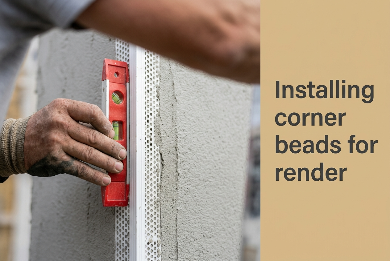
- Embed the profile. Press the bead firmly into the wet basecoat, nose first, ensuring full contact along the entire length. Use the flat side of a stainless-steel trowel to press the mesh wings into the adhesive, working from the nose outward to expel trapped air. Immediately check plumb with a spirit level and adjust before the mortar begins to set. For aluminium beads, use gentle taps with a rubber mallet if the profile resists seating into stiffer mortars.
- Lap the field mesh over the wings. The main fibreglass reinforcement mesh must overlap the bead's mesh wings by a minimum of 100 mm on each face. This overlap is non-negotiable — it is the primary mechanism that prevents cracking at the transition between the corner profile and the flat wall surface. The full mesh-overlap discipline across joints, scaffold lifts, and corner patches is covered in the fibreglass mesh overlap guide.
- Cure, prime, and finish. Allow the basecoat reinforcement layer to cure fully — typically 24 to 48 hours depending on ambient temperature and humidity. Apply primer in accordance with the render manufacturer's specifications, ensuring even coverage over the bead area. When applying the silicone or silicate-silicone topcoat, work the material up to and over the bead nose with consistent trowel pressure to avoid leaving a visible ridge or shadow line at the corner.
Key Takeaway: The 100 mm field-mesh overlap over the bead's integrated wings is the single most important detail in corner-bead installation — it is the mechanism that ties the corner into the wider tensile reinforcement plane and prevents the hairline cracks that run parallel to the arris within the first winter on UK facades. Measure the overlap with a tape rather than estimating by eye, and verify it before the topcoat hits the wall.
Pro Tips for Avoiding Common Installation Mistakes
The most frequent installation error on UK EWI projects is insufficient mesh overlap. When the reinforcement mesh does not extend far enough beyond the bead wings, a stress concentration develops at the overlap edge, producing a hairline crack that runs parallel to the corner within the first winter. Always maintain the 100 mm minimum and verify with a tape measure rather than estimating by eye. A second common mistake is mechanical fixing of beads with nails or screws driven through the insulation board — this creates a thermal bridge point and compromises the continuous insulation envelope. All major EWI system manufacturers, including Atlas and Ceresit, require adhesive-only fixing of corner beads within their certified systems. If a bead will not stay in position with adhesive alone, the basecoat consistency is too dry or the substrate is not properly prepared.
- Coordinate the profile sequence: Bellcast beads go in first to establish the lower datum, stop beads second at vertical render terminations, and corner beads third — see the dedicated bellcast bead water-protection guide for the lower-datum method and the render stop bead installation guide for the vertical-termination sequence. Reversing this order creates cold joints at the horizontal-to-vertical junction that crack during the first thermal cycle.
- Stagger butt joints away from stress zones: Where two bead lengths meet on a tall corner, overlap the mesh wings by 100 mm and stagger the nose joint by at least 50 mm. Never place a bead-to-bead joint within 300 mm of a window or door opening, as these are already high-stress zones where any added discontinuity initiates cracking.
- Pre-cut beads on a mitre saw the day before: Pre-cutting elevation-height beads in the workshop before basecoat day keeps the wet-mortar workflow uninterrupted and produces cleaner ends than on-site cutting under time pressure. Keep offcuts for patching around meter boxes and service penetrations.
- Trim with bead-cutting scissors, not tin snips: Standard tin snips crush the PVC nose and deform the arris geometry at cut ends, leaving a visible step that telegraphs through the topcoat. Bead-cutting scissors keep the nose square and protect the integrity of the arris on every cut.
Written by Mariusz Saja. Technically reviewed by Rafał Wyrzykowski. Last reviewed Jun 2026.
FAQ — Corner Bead Overlap, Cold Weather, and Compatibility
What is the minimum mesh overlap when installing corner beads on an EWI system?
The industry-standard minimum overlap between the corner bead's integrated mesh wings and the main wall reinforcement mesh is 100 mm on each side. This overlap ensures continuous tensile strength across the corner-to-wall transition and prevents the linear cracking that occurs when the two mesh layers are not adequately bonded together within the basecoat. On high-exposure elevations or buildings above three storeys, some system manufacturers recommend increasing this to 150 mm for additional security — confirm against the specific system certificate before ordering.
Can I use galvanised steel corner beads for external silicone render systems?
Galvanised steel beads are not recommended for external thin-coat render or EWI applications in the UK. The combination of high humidity, driving rain, and alkaline basecoat mortar accelerates corrosion of the zinc coating, eventually producing orange-brown rust stains that bleed through the topcoat after several wet seasons. PVC and aluminium profiles are the materials endorsed by major EWI system manufacturers for external corners exposed to UK weather conditions, and the cost differential is minimal across the full beads order.
How do I handle corner bead installation in cold weather below 5 °C?
When site temperatures drop below +5 °C, the basecoat mortar's hydration slows dramatically, extending setting times and increasing the risk of frost damage before the bead is fully encapsulated. Reduce your working section length to no more than 1.0 m, use a winter-grade or accelerated basecoat where the system manufacturer permits, and protect freshly installed beads with insulating blankets for at least 24 hours. Never attempt to install corner beads if the substrate temperature is at or below 0 °C, regardless of the air-temperature reading on the thermometer.
PVC or aluminium — which profile is right for which job?
PVC profiles are chemically inert in the high-pH basecoat environment and entirely corrosion-proof, which is why they are the default specification for external rendering and EWI in the UK. Aluminium beads offer greater rigidity and are typically selected for high-traffic ground-floor commercial facades or internal wet-plaster work where mechanical strength at the edge is the primary concern. For most residential and light-commercial EWI projects, PVC with integrated mesh delivers the best balance of installation speed, durability, and weather resistance — aluminium earns its place when the elevation faces sustained mechanical contact rather than just weather exposure.
How much do corner beads cost on a typical UK project?
Individual profiles range from approximately £1.70 for steel corners up to around £4.90 for specialist arched PVC beads with mesh, with standard PVC corner beads with mesh sitting around £3.00 per 2.5 m length. A typical three-bedroom semi-detached property takes 25–35 linear metres of corner bead across all elevations, so the full corner-bead specification represents a modest proportion of the overall facade materials budget. Approximate figures shown are working trade ranges subject to current pricing.
How do I install corner beads on curved or arched openings?
Curved window heads and arched openings require arched PVC corner beads with a notched or segmented spine that allows the profile to bend smoothly without kinking. Pre-form the profile to roughly match the curve before applying the basecoat bed, then press it into position section by section, checking the radius matches the opening geometry at each step. Use slightly more adhesive bed thickness on curves than on straight runs to accommodate minor flex variations, and embed the field mesh in shorter overlap sections to follow the curve continuously rather than as straight strips that would lift away at the apex.