
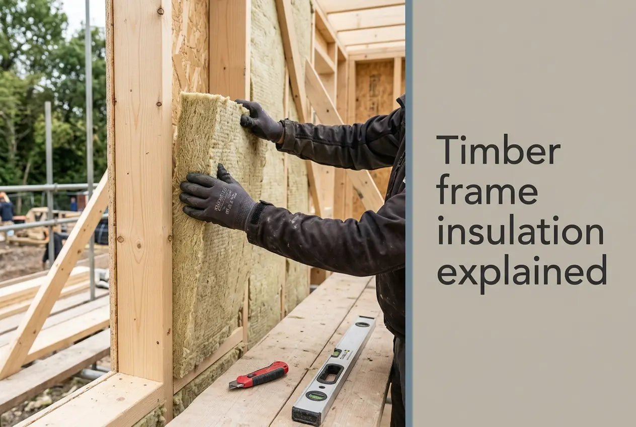
A rendered timber frame is a moisture system before it is a thermal one, and the layers that keep the studs dry are specified in a fixed order: breather membrane, ventilated cavity, carrier board, reinforcement, finish. Renders World supplies that build-up from the board outwards, including the vapour-open mineral wool insulation that lets the wall dry to the outside. The figures below come from the manufacturer's own installation guide for the carrier board, read in full for this revision.
Why a Rendered Timber Frame Needs a Drained, Vented Cavity
Timber frames stay dry behind render because of a vented cavity rather than despite it, and the STS render carrier board guide makes that cavity a condition of use: the board must have a cavity behind it, vented at both top and bottom. Where the board would otherwise finish flush with the wall below, the guide calls for battens giving a minimum 15 mm airflow gap at the base, so the cavity is never closed off at the point where water collects.
That gap does two jobs at once. Wind-driven rain that gets past the render runs down the back of the board and out at the base detail, and air movement through the same void carries away vapour that has diffused outward from the frame. The guide's base detail sets this out as a sequence — DPC, stop bead, and an insect mesh with a ventilation section — which is the arrangement that keeps the opening working without becoming an entry point.
A breather membrane sits behind the battens on most timber frame buildings, and the guide recommends confirming the need and the type with building control or the project engineer rather than treating it as automatic. Warranty requirements sit alongside the manufacturer's, so the applicable standards — the NHBC Standards library, for instance — are worth checking before the batten layout is fixed. The boards themselves come from the render carrier board range, and their job is to carry the finish while the void behind does the moisture work.
Setting Out Battens, Cavity Depth and Board Gaps
Batten layout is where the cavity depth, the fixing count and the board's tolerance for movement are all decided at once, so it repays getting right on paper. The guide recommends vertical battens as the default, with cross-battening available where a specific build-up or an existing cladding line has to be matched.
| Condition | Batten arrangement | Fixings per 2400 × 1200 sheet |
|---|---|---|
| England and Wales, most cases | Vertical battens at 600 mm centres | 27, horizontal orientation |
| Higher wind load or exposure | Vertical battens at 400 mm centres | 28, horizontal or vertical orientation |
| Scotland, Northern Ireland, Republic of Ireland | Minimum cavity depth 50 mm | By batten centre, as above |
The batten section itself is a minimum of 25 × 60 mm, with 60 mm wide by 25 mm deep the common size. Width matters more than it looks: the batten has to be broad enough to take a secure fixing into two adjacent boards while still leaving the gap between them, which is why a narrower batten causes trouble at every board joint on the elevation.
That gap is a 3–5 mm space on all sides of each board, and it is the detail that absorbs timber movement. Moisture and heat both move a timber substrate, and butt-jointed boards with nowhere to go push each other in or out of plane; with the gap present, the mesh layer in the render system absorbs what little movement transfers to the topcoat. On the 2400 × 1200 board, 28 fixings across 2.88 m² works out at 28 ÷ 2.88 = 9.7 fixings per square metre — a board-fixing density, entirely separate from the insulation fixing count, which is a wind-load calculation of its own.
Movement joints and exposure before rendering
Horizontal and vertical movement joints are required at 15 m spans maximum on most structures, or aligned with joints in the substrate behind, with the joint gap not exceeding 25 mm. Spacing and detail are confirmed with the render manufacturer or building control before installation.
The boards tolerate a realistic site programme. They can be left exposed for up to six months, and where rendering will not follow within two months the guide advises a PU adhesive between boards at installation to keep the joints weatherproof. Rendering sooner than that, the gaps are simply filled with the base coat mix, and the board must be dry, dust-free and undamaged before the render goes on.
Fixing the Carrier Board to Timber and Steel Frames
Frame material changes the fixing, and this is the one substitution that quietly undermines an otherwise correct build-up. The guide specifies a 3.95 × 38 mm self-drilling, self-countersinking screw into timber framework, and a 4.8 × 38 mm self-drilling, self-countersinking wingtip fixing into light steel framing. Both must be stainless steel or suitably treated for external use.
- Edge distance: fix 20 mm in from board edges as the recommendation, with 15 mm successfully tested — useful headroom when a batten line lands awkwardly.
- Matched screws: the 38 mm render board screws are the timber-frame length from the guide, packed in 250s.
- Board format: the 2400 × 1200 × 12 mm carrier board covers 2.88 m² and weighs 45 kg, so it is a two-person lift at scaffold height; the 1200 × 800 board covers 0.96 m² at 15.2 kg.
- SIP panels: the outer OSB layer is structural enough to take the batten fixings directly, then the build-up proceeds as standard timber frame.
The board is fibre cement to BS EN 12467:2016+A1:2016 at a density of 1.23 g/cm³, with a mean pull-through result of 1650 N and mean pull-out of 840 N, and a minimum life expectancy of 30 years. The full specification, fixing patterns and detail drawings are in the STS render carrier board product and installation guide.
How Airtightness and Vapour Movement Coexist
Sealing a wall against air movement and letting it dry outward are separate jobs on opposite sides of the insulation, which is why they can both be achieved fully. The air barrier belongs on the warm internal side, lapped and taped at junctions and service penetrations; the external layers are then selected to pass vapour rather than hold it.
Key Takeaway: Airtight inside, vapour-open outside, ventilated in between. The internal barrier stops warm moist air reaching the frame, the outer layers let whatever gets through diffuse away, and the vented cavity removes it — three mechanisms, each with its own layer.
The carrier board contributes almost nothing thermally and is not meant to: its declared thermal conductivity is 0.24149 W/mK to BS EN 12667:2001, giving an R-value of 0.0493 m²K/W at 12 mm. Reading that figure honestly is useful, because it confirms the board is a substrate rather than part of the insulation calculation, and the interstitial moisture profile of the whole build-up is a separate assessment a specifier runs before boarding.
Choosing the Insulation Layer for a Rendered Frame
The insulation has to be as vapour-open as the rest of the build-up, or it becomes the layer that holds moisture against the structure. Stone wool suits the role because its diffusion resistance is effectively that of open air: the Frontrock Plus Declaration of Performance declares a water vapour diffusion resistance factor of μ 1, alongside λD 0.035 W/mK under EN 13162:2012+A1:2015.
- Declared thermal resistance, Frontrock Plus: 1.40 m²K/W at 50 mm and 2.25 m²K/W at 80 mm, taken from the DoP's declared table rather than derived from thickness and lambda.
- Range scope: those figures are declared for Frontrock Plus. Renders World stocks Frontrock Super at 80, 100, 120 and 160 mm as well, and no Super DoP was retrieved for this revision, so its figures are confirmed against the document for the supplied batch at order.
- Adhesive: stone wool needs a cementitious adhesive rather than a foam one, since the open fibre structure gives foam nothing to key into.
- Finish: the guide recommends a thin coat silicone system over sand and cement, which sets solid and tends to crack over board joints — a flexible silicone render moves with the substrate instead.
Specify the Timber-Frame Facade as One System
Every figure above belongs to a different layer, and the wall only works when they are ordered together — batten section against cavity depth, fixing type against frame material, insulation against the diffusion path. Renders World holds the carrier boards, screws, stone wool, reinforcement and finish as one supply, so a build-up settled on paper arrives as a single specification rather than five part-orders.
- Start with the board and its fixings from the carrier board range, sized to your batten centres and frame material.
- Add the insulation depth your U-value assessment calls for, checked against the declared resistance rather than a calculated one.
- Place the detail in context with the solid-wall retrofit sequence for Victorian and Edwardian houses, which works through the same moisture logic on masonry.
- Compare the wider component ranges across the external wall insulation systems hub, where each collection owns one layer of the build-up.
Written by Mariusz Saja. Technically reviewed by Rafał Wyrzykowski. Last reviewed Aug 2026.
FAQ — Battens, Fixings and Cavity Depths on Timber Frames
How many screws does a full carrier board sheet need?
On 2400 × 1200 sheets, 28 fixings at 400 mm batten centres in either orientation, or 27 at 600 mm centres in horizontal orientation. Across the sheet's 2.88 m² that is roughly ten per square metre, which is a board-fixing figure and unrelated to insulation fixing density.
Does cavity depth change between England and Scotland?
Yes. The guide's batten sizing applies in England and Wales, and for Scotland, Northern Ireland and the Republic of Ireland it sets a minimum cavity depth of 50 mm. Confirming which applies before ordering battens avoids a resize once the membrane is on.
Which screw suits a light steel frame rather than timber?
A 4.8 × 38 mm self-drilling, self-countersinking wingtip fixing for steel framing, against 3.95 × 38 mm self-drilling and self-countersinking into timber. Either way the fixing is stainless steel or treated for external use, since it sits in a ventilated cavity for the life of the facade.
Can the boards stand exposed if the render is delayed?
They tolerate up to six months exposed. Where rendering will not start within two months of installation, the guide advises a PU adhesive between boards at the point of install, or an external grade joint filler and weatherproof tape on already-installed boards.
Can sand and cement render go onto a carrier board?
The bonding surface accepts cement-based products, but cement sets rigid and tends to crack at the board joints. A thin coat silicone system is the recommended route because it stays flexible over a substrate that moves seasonally, which is the behaviour any timber-backed facade has to accommodate.